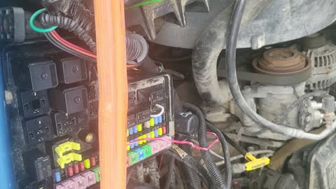
Crank no start?

Tiny
LONNIE CARR
  • MEMBER
  • 52 POSTS
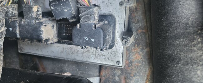
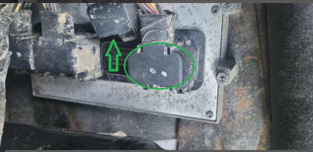
The connector is in my hand I measured the top right third pin in.
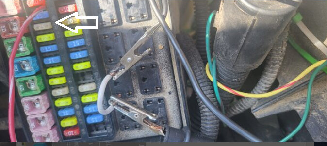
And the multimeter reads nothing. I have a jumper wire in 86 of the ASD. And I have an alligator clip hooked to that which is hooked to the positive end of the multi meter. And I'm using the negative probe to touch number 3. Is this correct?
Was this
answer
helpful?
Yes
No
Thursday, August 17th, 2023 AT 9:58 AM
Tiny
LONNIE CARR
  • MEMBER
  • 52 POSTS
Besides the actuator the only code that comes up is a p 0685.
Was this
answer
helpful?
Yes
No
Thursday, August 17th, 2023 AT 2:10 PM
Tiny
AL514
  • MECHANIC
  • 4,706 POSTS
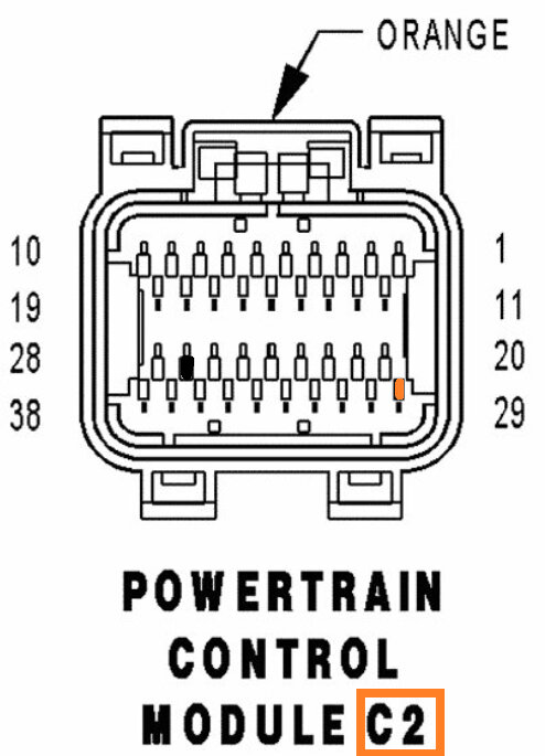
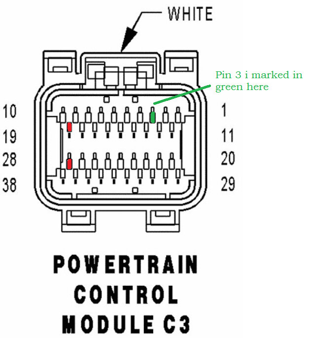
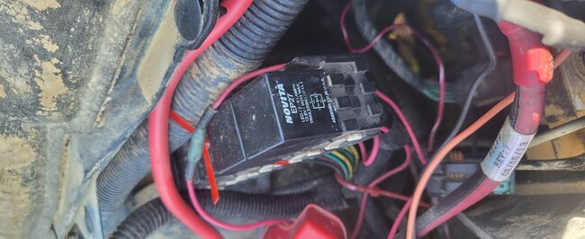
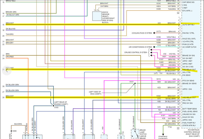
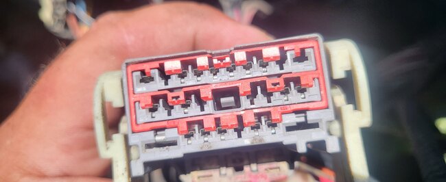
Okay, so sorry for the delay. I got fried yesterday working out in the sun, but if you can remove the back cover on the PCM connector, you can be 100 sure that you have the correct wire, because it will be that same brown/white wire coming from ASD pin 86, you will also be able to inspect the back of the wiring in the PCM connector as well, making sure there is no corrosion or open wiring there, but yes pin 3 would be the top right, 3rd pin in. If you are reading nothing, then it's an open circuit to the ASD relay. In these cases, I check the back of the PCM connector and do and Ohms check from there also, to verify you don't have an issue with that PCM connector pin. If that pin is pushed back into the connector for whatever reason, I believe you are on PCM connector C2 because of the Orange inside that connector. Service info states C3 should be white inside. So, check the connector next to that one. To your left.
Also, what's this pink/white wire running to? I didn't see this picture because the post started another page.
And I'm not sure what relay pins you have jumped out right there.
Was this
answer
helpful?
Yes
No
Friday, August 18th, 2023 AT 9:33 AM
Tiny
LONNIE CARR
  • MEMBER
  • 52 POSTS
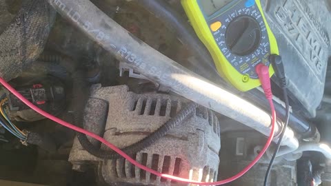
I Connected the Multimedia 200 and it reads nothing. I Disregard the other pictures in terminal video. The Red and white wire in the fuse box without looking is supposed to be. I think hooked up to 10- or 20-amp fuse. That Was added when I had a blade put on.
Was this
answer
helpful?
Yes
No
Saturday, August 19th, 2023 AT 8:55 AM
Tiny
LONNIE CARR
  • MEMBER
  • 52 POSTS
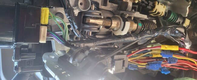
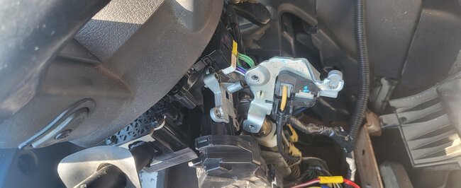
I also think something was said about the digger door digger being on period it. When I opened the door with the Ignition turned off. The door does not ding unless I push the key in further. Then it'll ding if I turn the key on the door dings. Also, what are those connectors that are Plugged in to the steering wheel at the column. The yellow one had brass terminals falling out of it when I unplugged it.
Was this
answer
helpful?
Yes
No
Saturday, August 19th, 2023 AT 9:16 AM
Tiny
LONNIE CARR
  • MEMBER
  • 52 POSTS
What about these relays next to the break booster?
Was this
answer
helpful?
Yes
No
Saturday, August 19th, 2023 AT 9:23 AM
Tiny
AL514
  • MECHANIC
  • 4,706 POSTS
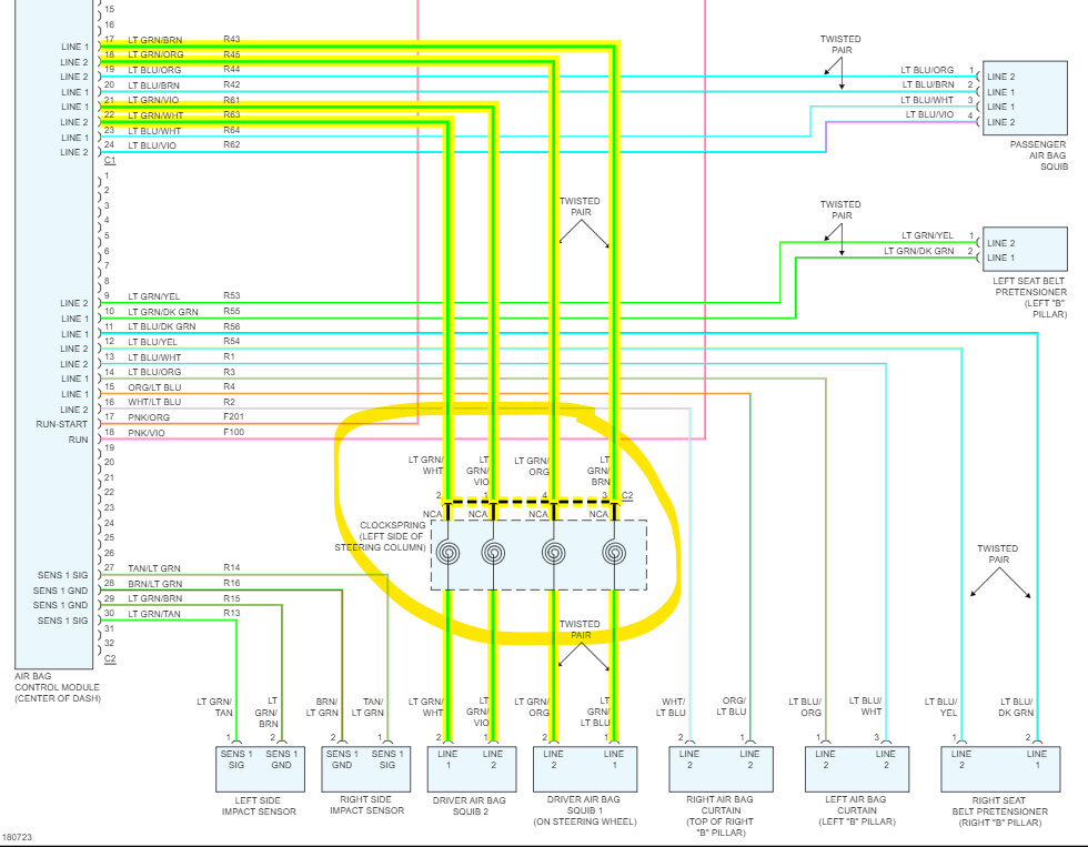
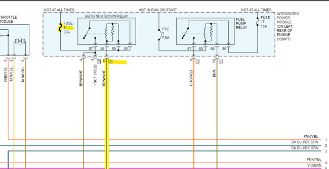
So, with your ASD relay to the PCM test, your meter is on a 20 million Ohm scale, so there is 1.6 million ohms of resistance on that circuit, that's an open/corroded circuit between the relay and PCM connector. The yellow connector I posted back a few, that's an air bag connector for the steering wheel airbag. You shouldn't have unplugged that with the battery still hooked up, I'm surprised the airbag didn't go off. But that's probably because the connector fell apart. But don't mess with that anymore. That needs to be repaired by a tech that is comfortable doing airbag SRS work. I'm not going to advise on that except to say that its very dangerous and if it goes off in your face you can get seriously hurt. So, leave that yellow connector out if the internal parts of the connector fell out. This is the diagram I posted on the last page about that.
As for the chime, it should sound with the key in the Ignition switch, it shouldn't need to be turned on, it should remind you that your key is still in the ignition switch.

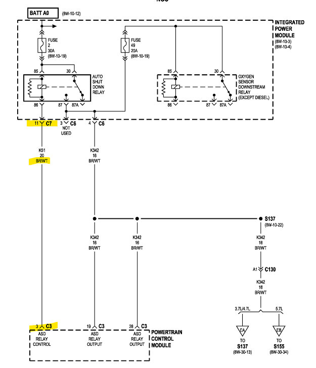
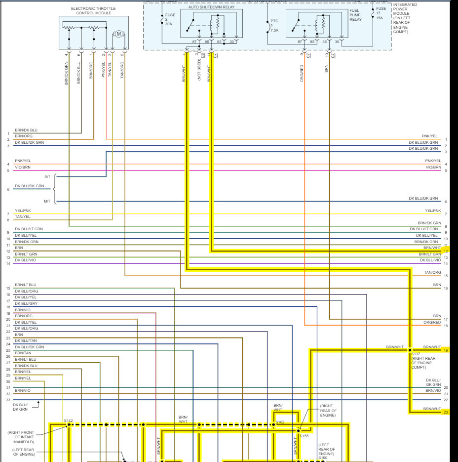
But the brown/white wire coming out the back of that white PCM connector is the ASD relay control wire, there are other brown/white wires coming out of that connector, unfortunately I don't know why manufacturers do that, but if you can remove the back cover on the PCM white connector, you can find pin 3 and try to follow that wire. The 2nd diagram is the OEM manufacturer diagram, it shows there are no connectors in between, so the first thing I would do is check underneath the relay/fuse box for any broken off wires, you can check continuity from pin 86 to under the relay box to find the correct pin. If it's not broken there, you'll have to follow that Brown/White wire from either the relay or the PCM pin 3. Follow the harness around and check any contact points where the harness is attached to brackets or areas where the harness is exposed.
These are tough cases because wires can be broken inside the harness without showing much on the outside of the insulation, but with resistance reading that high, there is a section of wiring that is corroded inside and that's why the relay is not being grounded by the PCM.
I have seen a lot of these broken under the fuse box, so that's where I would check first.
Was this
answer
helpful?
Yes
No
Saturday, August 19th, 2023 AT 10:35 AM
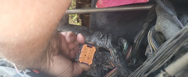
Tiny
LONNIE CARR
  • MEMBER
  • 52 POSTS
I will do that. Could I splice the wire on the back of the connector at the PCM and run it the relay box and hook it up to the 86 pin of the ASD?
Was this
answer
helpful?
Yes
No
Saturday, August 19th, 2023 AT 11:08 AM
Tiny
AL514
  • MECHANIC
  • 4,706 POSTS
Well, an overlay in this situation is 50/50 chance, because wherever this wire is broken or corroded there are almost other wires in that location that have succumb to the same conditions. There are 2 other Brown/White wires that run to the PCM that are power feeds from the ASD relay. They are labelled ASD Relay out. And considering all those wires are running from the same location to the PCM, if the area where the wire is damaged has a bunch of wires damaged there, you take a risk of shorting out that control wire to power. There goes the PCM. Did you check the control wire from Pin 3 to ground and from the relay to ground to see if either side is shorted to something. It's up to you, a quick fix like that can lead to you to having to find the original issue in the near future anyway. Check the underside of the fuse box first. See if it's broken or corroded on the underside of those pins.
Was this
answer
helpful?
Yes
No
Saturday, August 19th, 2023 AT 1:36 PM
Tiny
LONNIE CARR
  • MEMBER
  • 52 POSTS
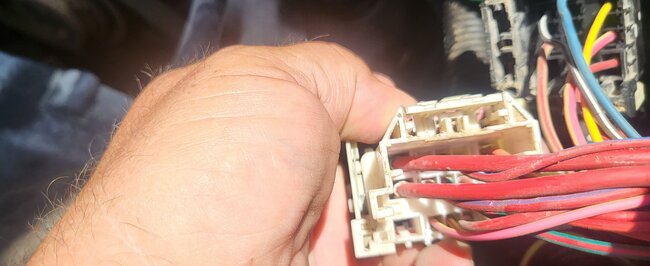
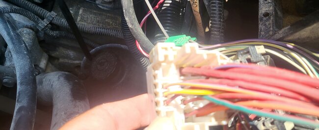
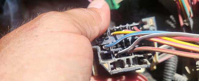
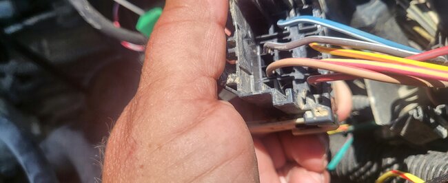
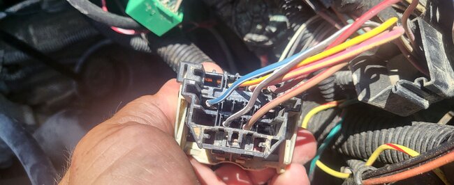
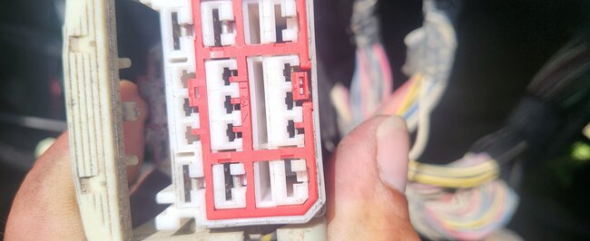
I will send pictures of the connectors shortly.
I'm flipping up in arms on what the problem is. I'm about ready to buy a new battery, cam sensor and crank sensor.
Was this
answer
helpful?
Yes
No
Wednesday, August 23rd, 2023 AT 10:22 AM
Tiny
LONNIE CARR
  • MEMBER
  • 52 POSTS
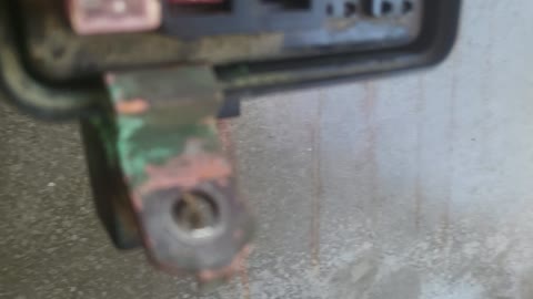
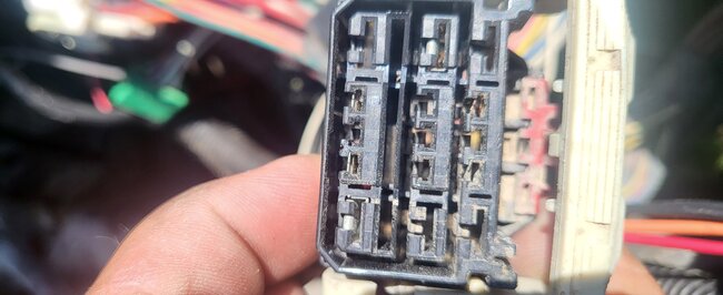
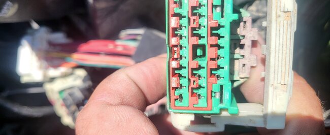
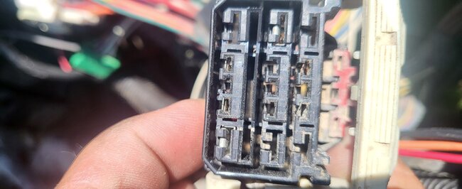
This is what I got.
Was this
answer
helpful?
Yes
No
Wednesday, August 23rd, 2023 AT 10:33 AM
Tiny
AL514
  • MECHANIC
  • 4,706 POSTS
Don't give up, never do that. Automotive diagnostics is never easy. Even after 20 years we all still learn new things on every vehicle. And here we have to adapt to every year make and model to figure out what's going on. If you want to try the overlay, go for it. You just have to at least cut each wire on both sides of the circuit. Just mark which wire it is with a piece of tape at the section where you are cutting it, so you remember where it is. Since you'll have to leave the original wire in the harness. Try the overlay and see if it works. If it doesn't then you know you're dealing with some other issue with the PCM not grounding the relay. If you didn't find any broken wires under the fuse panel or through the harness, then the wire is most likely broken inside the insulation. That can happen if there's even a tiny pin hole in the wiring insulation and it corroded inside. But don't start throwing parts at it. When that doesn't work you will be more frustrated. Almost anything can happen with vehicles, sometimes you have to step away, and come back to it. Instead of going down the rabbit hole as we call it. That happens to every single technicians' multiple times. But try your idea, just write down, or take pictures so you can go back over things later if needed.
Was this
answer
helpful?
Yes
No
Thursday, August 24th, 2023 AT 12:47 PM
Tiny
LONNIE CARR
  • MEMBER
  • 52 POSTS
I did wall away. After pulling the TIPM I looked at it and I'm not really sure how to remove the fuse panel from the rest of the unit.
Was this
answer
helpful?
Yes
No
Thursday, August 24th, 2023 AT 2:24 PM
Tiny
AL514
  • MECHANIC
  • 4,706 POSTS
The TIPM has an integrated fuse panel, the fuse contacts inside are usually a soldered trace type of board. It's a smart type of fuse panel. It's also on the data bus. It's probably something you don't want to try to take apart. To diagnose it you would just be checking its inputs and outputs on the connectors. Did you already try running an overlay on the ASD relay control wire to the PCM?
Was this
answer
helpful?
Yes
No
Thursday, August 24th, 2023 AT 3:30 PM
Tiny
LONNIE CARR
  • MEMBER
  • 52 POSTS
No, I haven't. When I walked away today, I went and mowed a cemetery. I lost my thought process on what to do so I will be waiting until tomorrow. I want to thank you again for all your help.
Was this
answer
helpful?
Yes
No
Thursday, August 24th, 2023 AT 4:43 PM
Tiny
AL514
  • MECHANIC
  • 4,706 POSTS
Well, I'm sorry I couldn't be more helpful. Seems like this summer with the extra high heat there have been many cases like yours, and actually on many GM 5.3 and 5.7 1500 series, and all module issues like this, I think these trucks may have the most problems I've ever seen. Even the new ones, just poorly designed, I guess.
With you being able to jump the relay contacts and make everything work, that means the 2 wires that come from the relay that supply power to the PCM are working as well. I believe one of them or both is for the PCM to see voltage from the relay. Because I know these can set codes for the ASD relay circuits if that power doesn't show up on those 2 inputs. So, it's either that the relay ground control wire is open somewhere, or the PCM cannot ground it due to a bad PCM driver. Running the overlay at this point is how we'll know what the fault actually is. If the overlay blows the Fuse number 2, then you know there are other circuit issues, but I don't think it will if the wire is cut from both sides and basically eliminated from the circuit. I haven't done many overlays, I always enjoyed troubleshooting for the most part. But we've checked everything else.
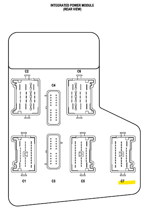
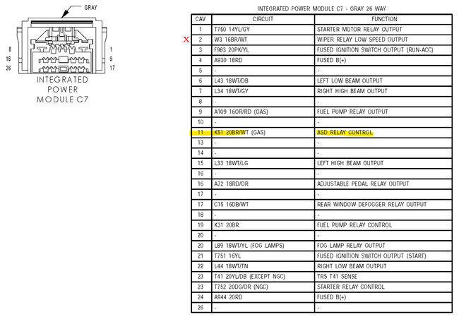
This connector C7 pin 11 is the wire you need to overlay.
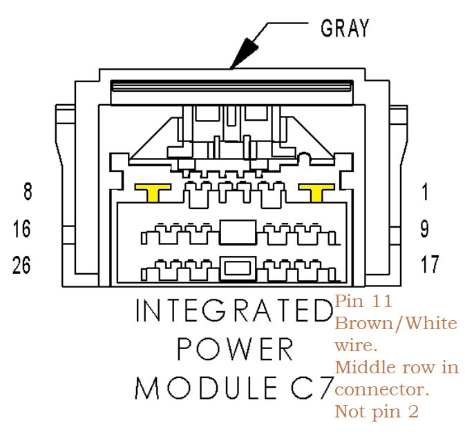
And just to confuse you a bit more, jk, here's the pinout for the TIPM connector C7. Just be aware there are 2 Brown/White wires in this connector. You want pin 11 which is going to be in the middle row, not pin 2 which will be in either the top or bottom row.
Pin 11 is the ASD control wire to the PCM. So, you don't have to dig around too much because there are a bunch of other wires that are Brown/White. I don't know why manufacturers have to do that, at least in the same connector. But they do.
Was this
answer
helpful?
Yes
No
Friday, August 25th, 2023 AT 12:50 PM
Tiny
LONNIE CARR
  • MEMBER
  • 52 POSTS
Just to be clear, I'm cutting the brown/white wire from the C7 Connector on the fuse box that runs to the PCM C3 pin 3 correct? Then I'm running a new wire and splicing that together and in theory the truck should start?
Was this
answer
helpful?
Yes
No
Friday, August 25th, 2023 AT 5:12 PM
Tiny
AL514
  • MECHANIC
  • 4,706 POSTS
Yes, but be sure you're on the correct wire. There a multiple brown/white wires coming from the TIPM going to the PCM. Pin 11 is in the middle row on C7. You can also check the resistance from the C7 pin 11 to the PCM connector and see if there's high resistance or an open circuit. If I remember correctly when you checked it from the ASD relay pin you had 1.6 M Ohms to the PCM connector. So if you have lower resistance from the C7 connector you know the issue is inside the TIPM.
Was this
answer
helpful?
Yes
No
Saturday, August 26th, 2023 AT 11:01 AM
Tiny
LONNIE CARR
  • MEMBER
  • 52 POSTS
I hooked everything back up last night and tried jumping the ASD and now it doesn't start at all. P0685 and 3 actuator codes but I don't remember the #'s.
Was this
answer
helpful?
Yes
No
Saturday, August 26th, 2023 AT 11:55 AM
Tiny
LONNIE CARR
  • MEMBER
  • 52 POSTS
Evidently it does start. I must have had a bad connection last night. Or the battery was just low. Obviously, the idle is a little weird without the breather on and stuff. You mentioned checking the resistance from the C7 pin 11 to the PCM connector. There's a lot of different numbers, letters, and colors. You're going to have to be a little more specific. I'm sorry I just want to make sure that I'm hooking it up correctly. I know. C7 pen 11 Where do you mean when you say PCM connector and how do I test it?
Was this
answer
helpful?
Yes
No
Saturday, August 26th, 2023 AT 2:21 PM

Please login or register to post a reply.

Sponsored links