Crank no start?

2004 DODGE RAM
110,000 MILES • 5.7L • V8 • 4WD • AUTOMATIC
Advertisement
Avatar
LONNIE CARR
  • MEMBER
  • 52 POSTS
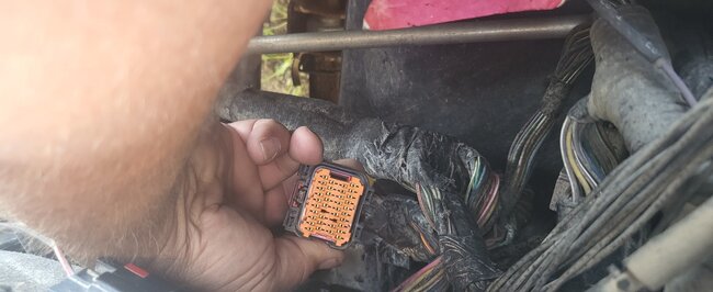
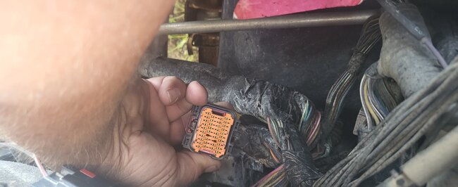
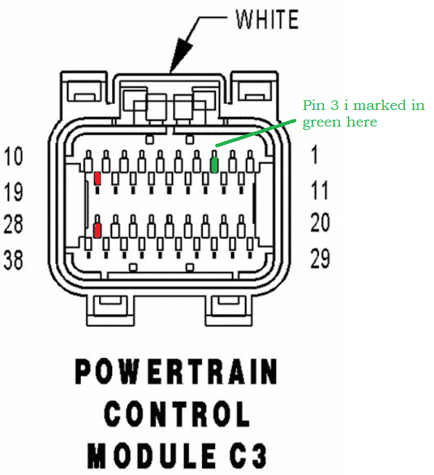
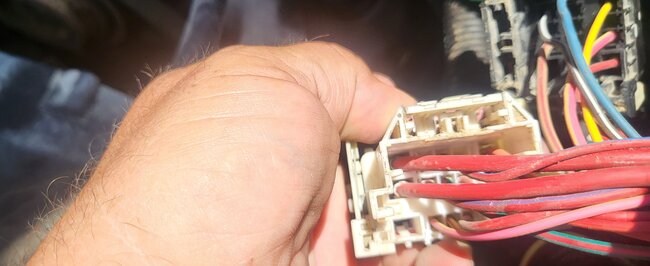
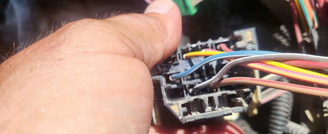
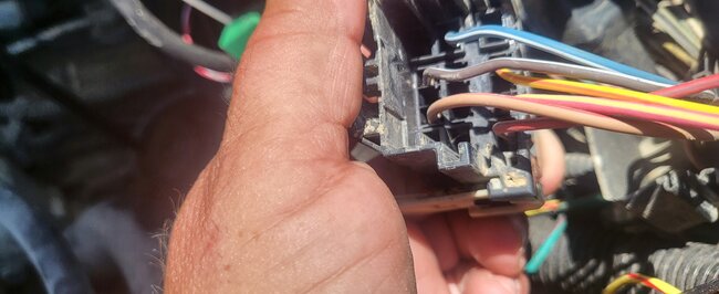
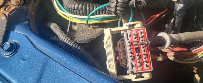
The connector is in my hand I measured the top right third pin in.
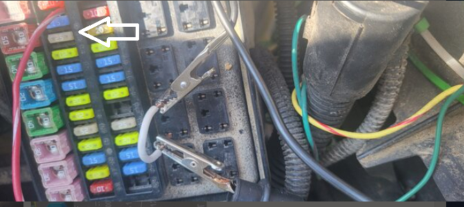
And the multimeter reads nothing. I have a jumper wire in 86 of the ASD. And I have an alligator clip hooked to that which is hooked to the positive end of the multi meter. And I'm using the negative probe to touch number 3. Is this correct?
Aug 17, 2023 at 2:58 AM
Avatar
LONNIE CARR
  • MEMBER
  • 52 POSTS
Besides the actuator the only code that comes up is a p 0685.
Aug 17, 2023 at 7:10 AM
Avatar
AL514
  • Experienced Mechanic
  • 5,639 POSTS
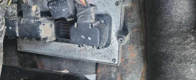
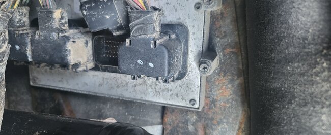
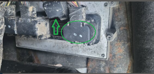
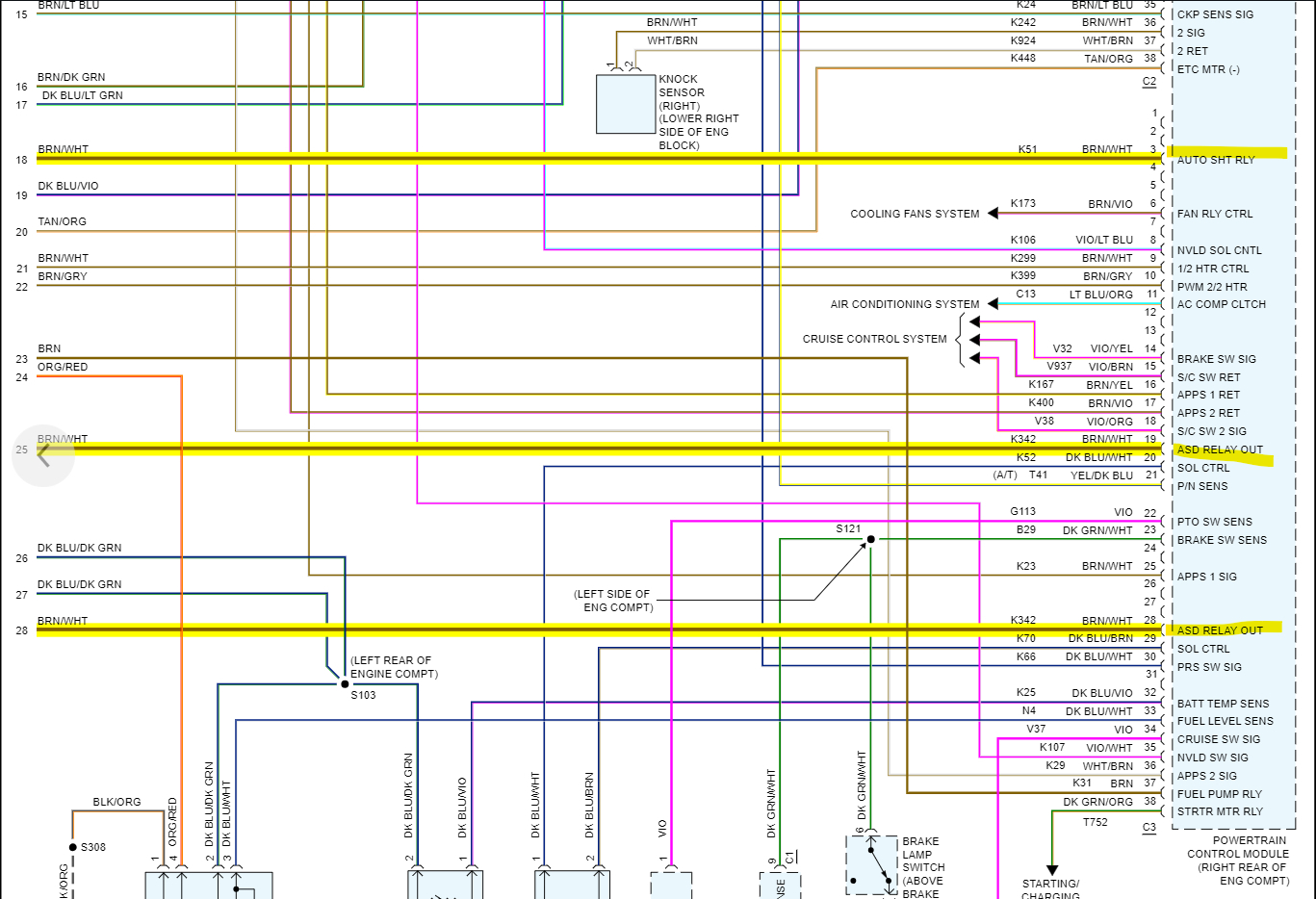
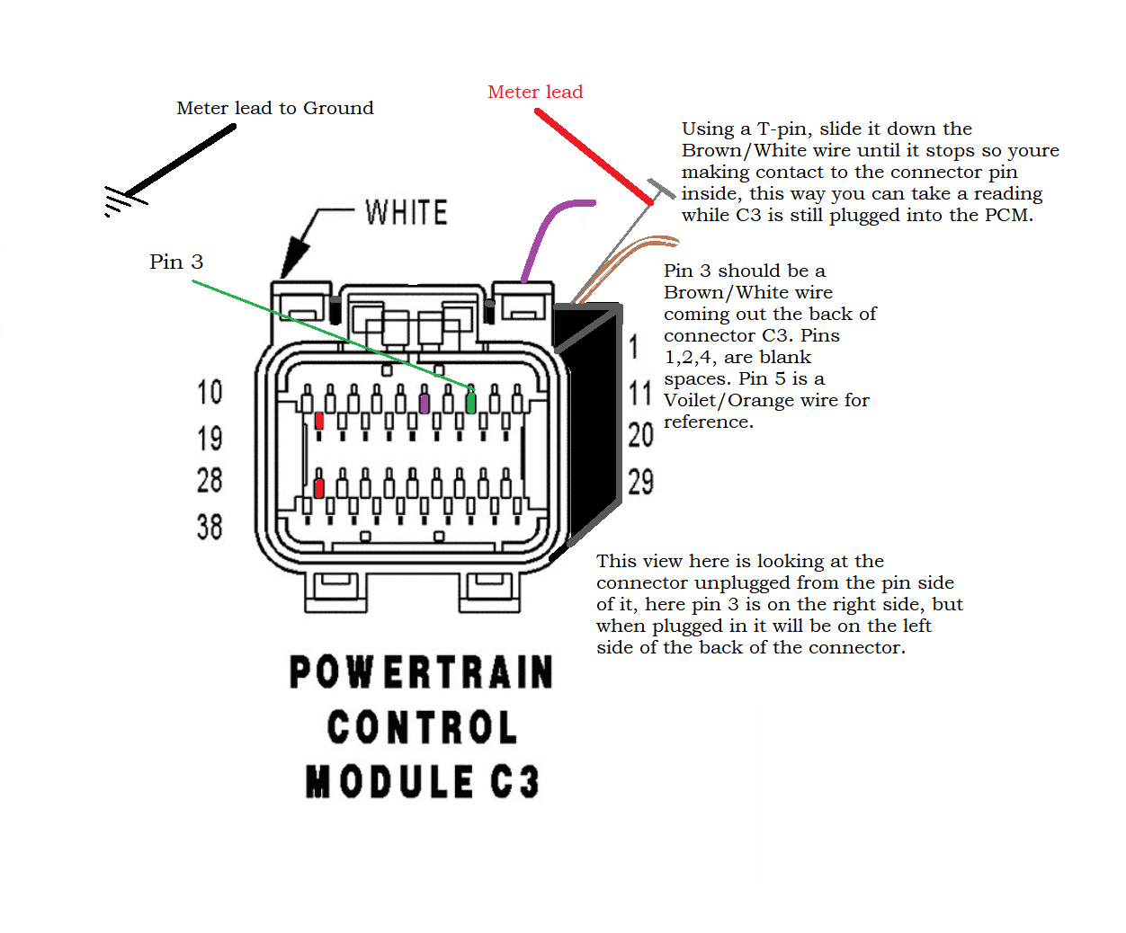
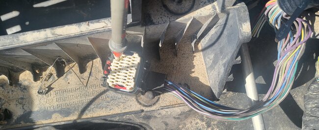
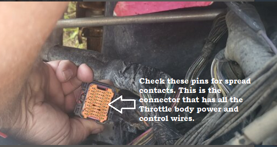
Okay, so sorry for the delay. I got fried yesterday working out in the sun, but if you can remove the back cover on the PCM connector, you can be 100 sure that you have the correct wire, because it will be that same brown/white wire coming from ASD pin 86, you will also be able to inspect the back of the wiring in the PCM connector as well, making sure there is no corrosion or open wiring there, but yes pin 3 would be the top right, 3rd pin in. If you are reading nothing, then it's an open circuit to the ASD relay. In these cases, I check the back of the PCM connector and do and Ohms check from there also, to verify you don't have an issue with that PCM connector pin. If that pin is pushed back into the connector for whatever reason, I believe you are on PCM connector C2 because of the Orange inside that connector. Service info states C3 should be white inside. So, check the connector next to that one. To your left.
Also, what's this pink/white wire running to? I didn't see this picture because the post started another page.
And I'm not sure what relay pins you have jumped out right there.
Aug 18, 2023 at 2:33 AM
Avatar
LONNIE CARR
  • MEMBER
  • 52 POSTS
I Connected the Multimedia 200 and it reads nothing. I Disregard the other pictures in terminal video. The Red and white wire in the fuse box without looking is supposed to be. I think hooked up to 10- or 20-amp fuse. That Was added when I had a blade put on.
Aug 19, 2023 at 1:55 AM
Avatar
LONNIE CARR
  • MEMBER
  • 52 POSTS
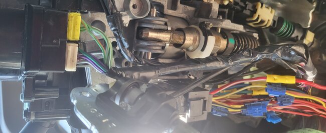
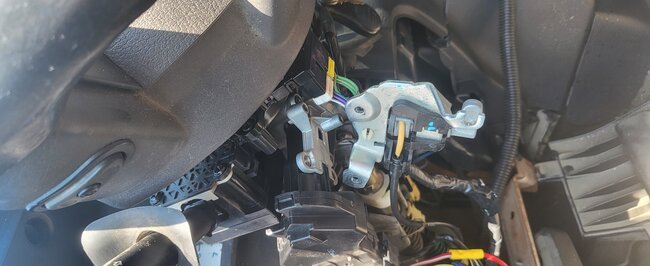
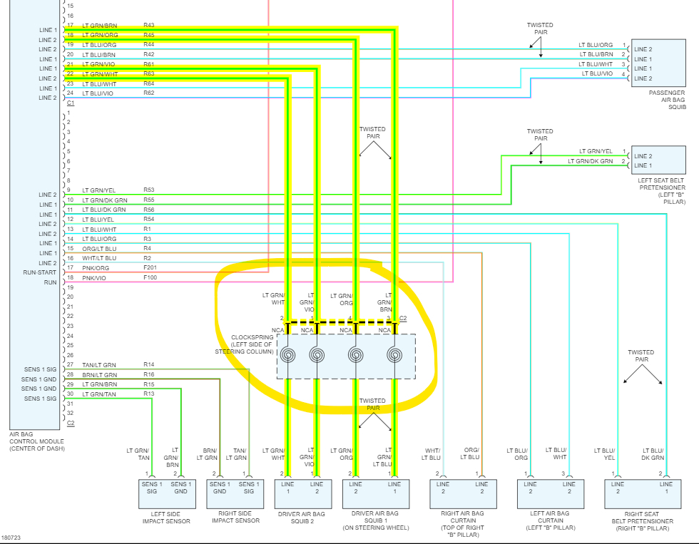
I also think something was said about the digger door digger being on period it. When I opened the door with the Ignition turned off. The door does not ding unless I push the key in further. Then it'll ding if I turn the key on the door dings. Also, what are those connectors that are Plugged in to the steering wheel at the column. The yellow one had brass terminals falling out of it when I unplugged it.
Aug 19, 2023 at 2:16 AM
Avatar
LONNIE CARR
  • MEMBER
  • 52 POSTS
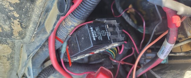
What about these relays next to the break booster?
Aug 19, 2023 at 2:23 AM
Avatar
AL514
  • Experienced Mechanic
  • 5,639 POSTS
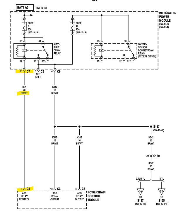
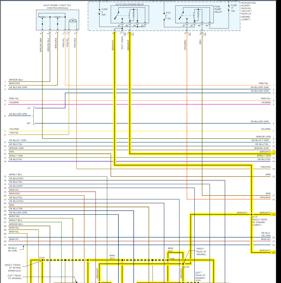
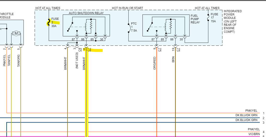
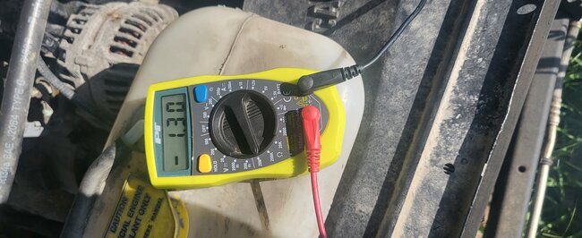
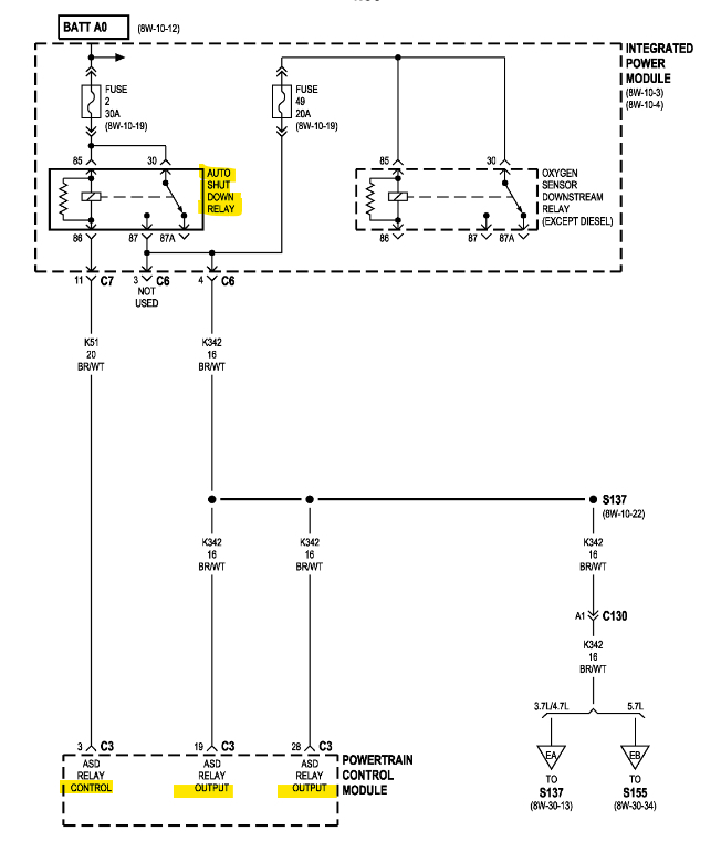
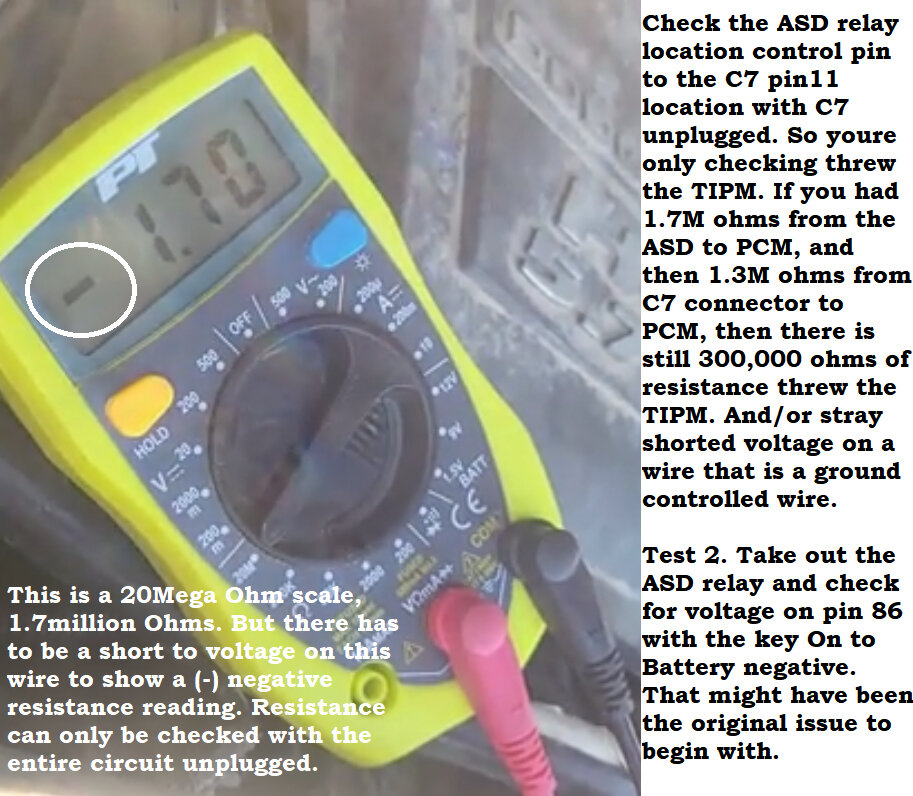
So, with your ASD relay to the PCM test, your meter is on a 20 million Ohm scale, so there is 1.6 million ohms of resistance on that circuit, that's an open/corroded circuit between the relay and PCM connector. The yellow connector I posted back a few, that's an air bag connector for the steering wheel airbag. You shouldn't have unplugged that with the battery still hooked up, I'm surprised the airbag didn't go off. But that's probably because the connector fell apart. But don't mess with that anymore. That needs to be repaired by a tech that is comfortable doing airbag SRS work. I'm not going to advise on that except to say that its very dangerous and if it goes off in your face you can get seriously hurt. So, leave that yellow connector out if the internal parts of the connector fell out. This is the diagram I posted on the last page about that.
As for the chime, it should sound with the key in the Ignition switch, it shouldn't need to be turned on, it should remind you that your key is still in the ignition switch.

But the brown/white wire coming out the back of that white PCM connector is the ASD relay control wire, there are other brown/white wires coming out of that connector, unfortunately I don't know why manufacturers do that, but if you can remove the back cover on the PCM white connector, you can find pin 3 and try to follow that wire. The 2nd diagram is the OEM manufacturer diagram, it shows there are no connectors in between, so the first thing I would do is check underneath the relay/fuse box for any broken off wires, you can check continuity from pin 86 to under the relay box to find the correct pin. If it's not broken there, you'll have to follow that Brown/White wire from either the relay or the PCM pin 3. Follow the harness around and check any contact points where the harness is attached to brackets or areas where the harness is exposed.
These are tough cases because wires can be broken inside the harness without showing much on the outside of the insulation, but with resistance reading that high, there is a section of wiring that is corroded inside and that's why the relay is not being grounded by the PCM.
I have seen a lot of these broken under the fuse box, so that's where I would check first.
Aug 19, 2023 at 3:35 AM
Avatar
LONNIE CARR
  • MEMBER
  • 52 POSTS
I will do that. Could I splice the wire on the back of the connector at the PCM and run it the relay box and hook it up to the 86 pin of the ASD?
Aug 19, 2023 at 4:08 AM
Avatar
AL514
  • Experienced Mechanic
  • 5,639 POSTS
Well, an overlay in this situation is 50/50 chance, because wherever this wire is broken or corroded there are almost other wires in that location that have succumb to the same conditions. There are 2 other Brown/White wires that run to the PCM that are power feeds from the ASD relay. They are labelled ASD Relay out. And considering all those wires are running from the same location to the PCM, if the area where the wire is damaged has a bunch of wires damaged there, you take a risk of shorting out that control wire to power. There goes the PCM. Did you check the control wire from Pin 3 to ground and from the relay to ground to see if either side is shorted to something. It's up to you, a quick fix like that can lead to you to having to find the original issue in the near future anyway. Check the underside of the fuse box first. See if it's broken or corroded on the underside of those pins.
Aug 19, 2023 at 6:36 AM
Avatar
LONNIE CARR
  • MEMBER
  • 52 POSTS
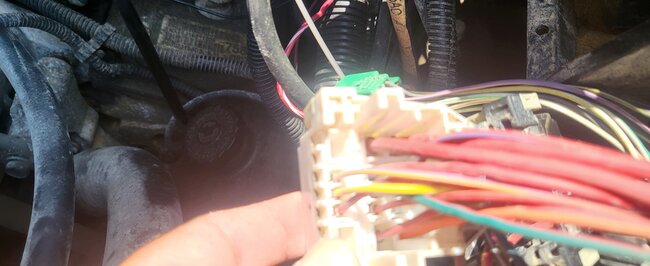
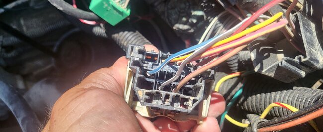
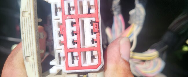
I will send pictures of the connectors shortly.
I'm flipping up in arms on what the problem is. I'm about ready to buy a new battery, cam sensor and crank sensor.
Aug 23, 2023 at 3:22 AM
Avatar
LONNIE CARR
  • MEMBER
  • 52 POSTS
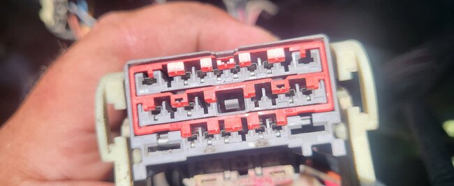
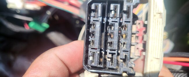
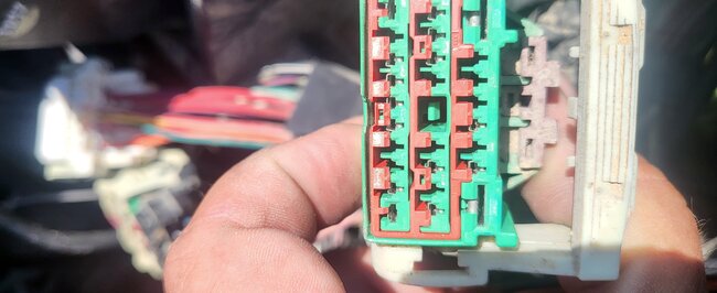
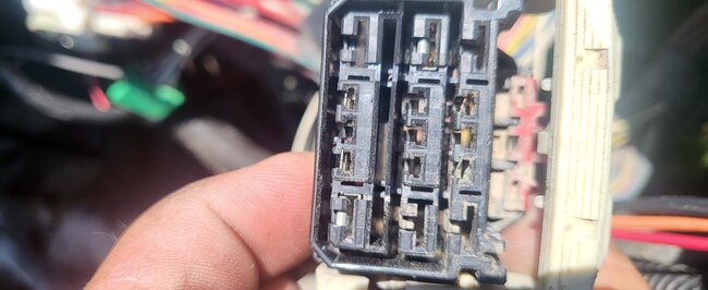
This is what I got.
Aug 23, 2023 at 3:33 AM
Avatar
AL514
  • Experienced Mechanic
  • 5,639 POSTS
Don't give up, never do that. Automotive diagnostics is never easy. Even after 20 years we all still learn new things on every vehicle. And here we have to adapt to every year make and model to figure out what's going on. If you want to try the overlay, go for it. You just have to at least cut each wire on both sides of the circuit. Just mark which wire it is with a piece of tape at the section where you are cutting it, so you remember where it is. Since you'll have to leave the original wire in the harness. Try the overlay and see if it works. If it doesn't then you know you're dealing with some other issue with the PCM not grounding the relay. If you didn't find any broken wires under the fuse panel or through the harness, then the wire is most likely broken inside the insulation. That can happen if there's even a tiny pin hole in the wiring insulation and it corroded inside. But don't start throwing parts at it. When that doesn't work you will be more frustrated. Almost anything can happen with vehicles, sometimes you have to step away, and come back to it. Instead of going down the rabbit hole as we call it. That happens to every single technicians' multiple times. But try your idea, just write down, or take pictures so you can go back over things later if needed.
Aug 24, 2023 at 5:47 AM
Avatar
LONNIE CARR
  • MEMBER
  • 52 POSTS
I did wall away. After pulling the TIPM I looked at it and I'm not really sure how to remove the fuse panel from the rest of the unit.
Aug 24, 2023 at 7:24 AM
Avatar
AL514
  • Experienced Mechanic
  • 5,639 POSTS
The TIPM has an integrated fuse panel, the fuse contacts inside are usually a soldered trace type of board. It's a smart type of fuse panel. It's also on the data bus. It's probably something you don't want to try to take apart. To diagnose it you would just be checking its inputs and outputs on the connectors. Did you already try running an overlay on the ASD relay control wire to the PCM?
Aug 24, 2023 at 8:30 AM
Avatar
LONNIE CARR
  • MEMBER
  • 52 POSTS
No, I haven't. When I walked away today, I went and mowed a cemetery. I lost my thought process on what to do so I will be waiting until tomorrow. I want to thank you again for all your help.
Aug 24, 2023 at 9:43 AM
Avatar
AL514
  • Experienced Mechanic
  • 5,639 POSTS
Well, I'm sorry I couldn't be more helpful. Seems like this summer with the extra high heat there have been many cases like yours, and actually on many GM 5.3 and 5.7 1500 series, and all module issues like this, I think these trucks may have the most problems I've ever seen. Even the new ones, just poorly designed, I guess.
With you being able to jump the relay contacts and make everything work, that means the 2 wires that come from the relay that supply power to the PCM are working as well. I believe one of them or both is for the PCM to see voltage from the relay. Because I know these can set codes for the ASD relay circuits if that power doesn't show up on those 2 inputs. So, it's either that the relay ground control wire is open somewhere, or the PCM cannot ground it due to a bad PCM driver. Running the overlay at this point is how we'll know what the fault actually is. If the overlay blows the Fuse number 2, then you know there are other circuit issues, but I don't think it will if the wire is cut from both sides and basically eliminated from the circuit. I haven't done many overlays, I always enjoyed troubleshooting for the most part. But we've checked everything else.
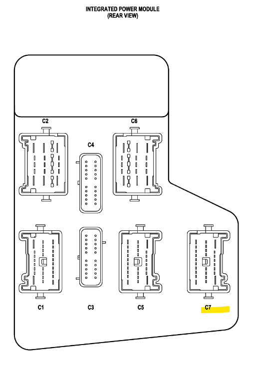
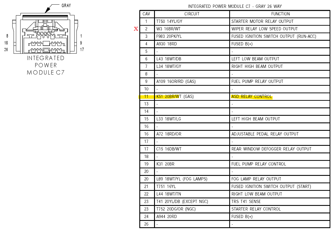
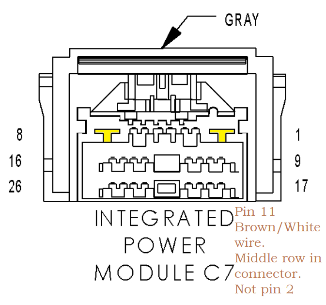
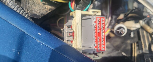
This connector C7 pin 11 is the wire you need to overlay.
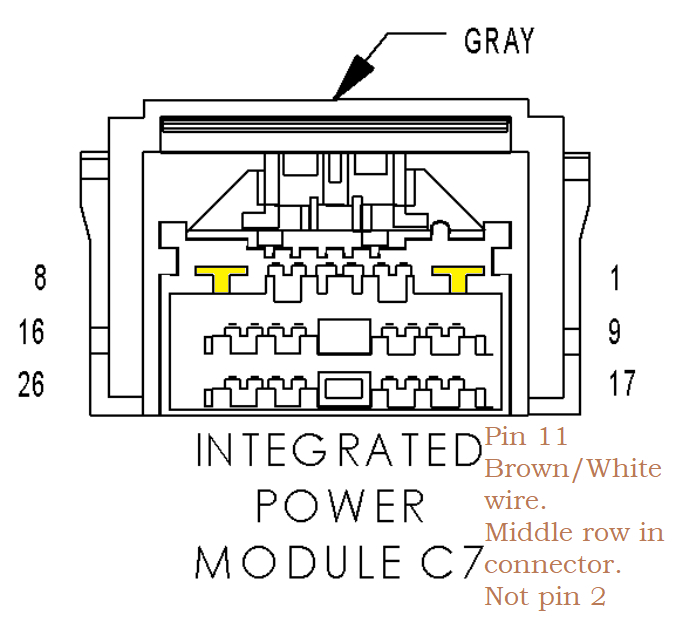
And just to confuse you a bit more, jk, here's the pinout for the TIPM connector C7. Just be aware there are 2 Brown/White wires in this connector. You want pin 11 which is going to be in the middle row, not pin 2 which will be in either the top or bottom row.
Pin 11 is the ASD control wire to the PCM. So, you don't have to dig around too much because there are a bunch of other wires that are Brown/White. I don't know why manufacturers have to do that, at least in the same connector. but they do.
Aug 25, 2023 at 5:50 AM
Avatar
LONNIE CARR
  • MEMBER
  • 52 POSTS
Just to be clear, I'm cutting the brown/white wire from the C7 Connector on the fuse box that runs to the PCM C3 pin 3 correct? Then I'm running a new wire and splicing that together and in theory the truck should start?
Aug 25, 2023 at 10:12 AM
Avatar
AL514
  • Experienced Mechanic
  • 5,639 POSTS
Yes, but be sure you're on the correct wire. There a multiple brown/white wires coming from the TIPM going to the PCM. Pin 11 is in the middle row on C7. You can also check the resistance from the C7 pin 11 to the PCM connector and see if there's high resistance or an open circuit. If I remember correctly when you checked it from the ASD relay pin you had 1.6 M Ohms to the PCM connector. So if you have lower resistance from the C7 connector you know the issue is inside the TIPM.
Aug 26, 2023 at 4:01 AM
Avatar
LONNIE CARR
  • MEMBER
  • 52 POSTS
I hooked everything back up last night and tried jumping the ASD and now it doesn't start at all. P0685 and 3 actuator codes but I don't remember the #'s.
Aug 26, 2023 at 4:55 AM
Avatar
LONNIE CARR
  • MEMBER
  • 52 POSTS
Evidently it does start. I must have had a bad connection last night. Or the battery was just low. Obviously, the idle is a little weird without the breather on and stuff. You mentioned checking the resistance from the C7 pin 11 to the PCM connector. There's a lot of different numbers, letters, and colors. You're going to have to be a little more specific. I'm sorry I just want to make sure that I'm hooking it up correctly. I know. C7 pen 11 Where do you mean when you say PCM connector and how do I test it?
Aug 26, 2023 at 7:21 AM
Avatar
AL514
  • Experienced Mechanic
  • 5,639 POSTS
The same way you tested it the first time, C7 pin 11 connector unplugged to PCM connector C3 pin 3 checking the resistance of the circuit. Ohms setting, if it doesn't read set the meter to a higher resistance setting. It sounds like you have pin fitment issues if it was a not start after moving the connectors and harness around. Same wire, same color, we're only dealing with this one wire the entire time here. P0685 is just the ASD circuit code again. If you find very low resistance to the PCM, you might be dealing with internal circuit issues with the TIPM, they're junk, but see what you get first.
Aug 27, 2023 at 1:54 AM
Avatar
LONNIE CARR
  • MEMBER
  • 52 POSTS
C three pin three / C seven pin eleven. My next step is to cut the wires off the back of the connector a couple of inches down and check for resistance through the actual wired wire instead of lead the lead. Or excuse me, pinned a pin. And then I'm going to hook up a new wire and check that way also. If needed.... After I hear back from you.
Aug 27, 2023 at 7:32 AM
Avatar
AL514
  • Experienced Mechanic
  • 5,639 POSTS
Yeah, check whatever you need to. I was just curious what type of resistance reading you get from the connector's vs the ASD relay location. With a vehicle that's getting to be 20 years old there will continue to be wiring and connector issues. Especially if you live up north where they use a lot of salt from the roads. Since I've moved south, I barely see any of those type of problems anymore. But I did for many years. Every vehicle that came in was a rusted-out mess underneath. So, investing in some basic tools for testing, i.e. test light, back probing pins, maybe an amp clamp. Will help in the future to make these types of issues easier to diagnose. I will rarely, if ever do resistance testing on a circuit unless it's checking for an open circuit or a short to ground. But YouTube is completely filled with every type of automotive testing you can imagine. So do some searches for automotive circuit testing and diagnostics. There is so much free information out there. I think I learned more in the last 10 years than in my first 10 years. Plus, if you enjoy being able to repair your own vehicle, you save a ton of money and its satisfying work. But anyway, let me know what you get on your circuit checking.

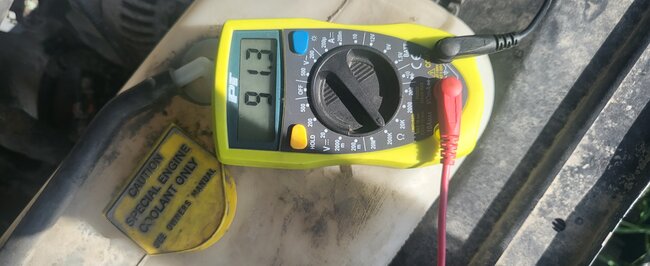
What are these readings from? I see about 91k Ohms on one of them, and I think 1.3M Ohms on the other?
Aug 28, 2023 at 2:06 AM
Avatar
LONNIE CARR
  • MEMBER
  • 52 POSTS
Here's the new code.
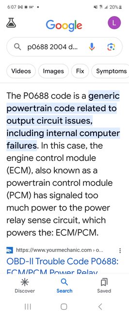
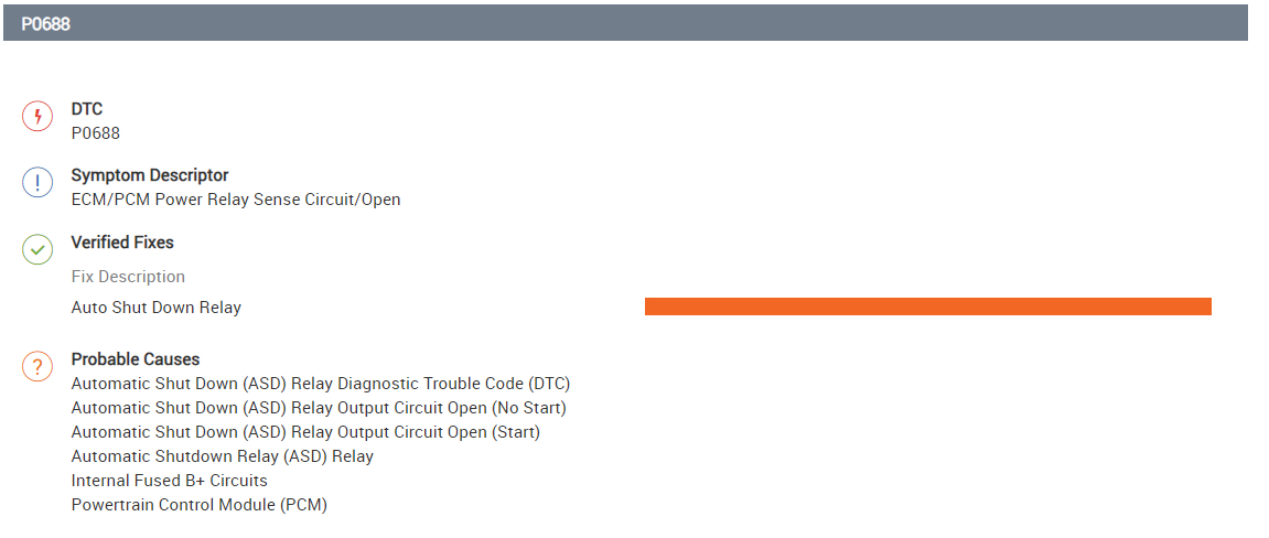
P 0688. And the 91k and -1.3m Were the measurements that I read? The resistant homes from C7 pin 11 to see 3 pin, the bottom of the tip Em. To the PCM. Now, I'm getting too much juice, please explain.
Aug 29, 2023 at 9:11 AM
Avatar
LONNIE CARR
  • MEMBER
  • 52 POSTS
Here's the new code.
P 0688 . And the 91k and -1.3m Were the measurements that I read? The resistant homes from C7 pin 11 to see 3 pin, the bottom of the tip Em. To the p c m. Now, I'm getting too much juice, please explain.
Aug 29, 2023 at 9:12 AM
Avatar
LONNIE CARR
  • MEMBER
  • 52 POSTS
Oh, I forgot to tell you that code is from me. Splicing the brown white C7 pin 11 to the C3 pin 3. I cut the wire on the bottom of the TIPM and spliced it and ran it to the PCM And did the same there on C3 pin 3.
Aug 29, 2023 at 9:15 AM
Avatar
AL514
  • Experienced Mechanic
  • 5,639 POSTS
The code P0668 is not a "too much power code". You're reading a generic basic OBD2 code definition. It's still the same ASD relay sense Circuit/Open code that been happening. There are 2 circuits that come off the power feed from the relay that feed 12v to 2 different input circuits to the PCM. Did the overlay not work?
If the PCM is not grounding the ASD relay, that code shows up because the ASD relay is not activating. You have to be a 100% sure on your splice connection. It needs to be crimped correctly and very tight as well as heat shrinked so no moisture gets into the wire. I would recheck your resistance reading from C7 to PCM C3 again and make sure the splice is good. If it is then either the PCM has a bad ground, the PCM driver that grounds the ASD relay has failed inside the computer, or there is a pin fitment issue at the TIPM or PCM.

Something else to check is the ASD relay location resistance check to the TIPM C7 pin 11, that will check the resistance through the TIPM for the control wire for the ASD relay. If there is a bad or cracked solder joint inside the TIPM, or corrosion you will have high resistance. Try reconnecting the TIPM connectors as well, you had an issue with that before. You may not notice it, but every time those connectors are unplugged and plugged back in you have moved all those wires, the section of harness and the TIPM around and nothing is ever perfect with connectors. Not every pin is always exactly the tension it should be or the perfect tightness around the pins.
These connectors are in fact designed not to be disconnected and reconnected ever after they leave the factory. I have researched and read up on engineers and how these vehicles come from the manufacturer. They say that each connector is designed so it should not be disconnected more than 3 times in total in the life of the vehicle.
But they are not technicians and don't have to fix these things. So going by those rules is impossible. So, there are variables that need to be taken into consideration. If the circuit doesn't not work with the PCM, you need to determine why.
This is where I would back probe the PCM connector pin 3 and with a voltmeter set on DC volts connected to battery negative, key On, does that PCM wire become Grounded.
It has to be checked on DC volts you can't measure resistance with a circuit plugged in. You have to measure voltage drop to battery negative from C3 pin 3.
Aug 29, 2023 at 10:17 AM
Avatar
LONNIE CARR
  • MEMBER
  • 52 POSTS
Yes, did it not load?
Sep 3, 2023 at 12:47 PM
Avatar
LONNIE CARR
  • MEMBER
  • 52 POSTS
I've been busy so the last info I have is crank no start only codes were, I think p2112 2106 and another one. All to do switch actuator. Still starts jumping the ASD.
Sep 3, 2023 at 12:52 PM
Avatar
AL514
  • Experienced Mechanic
  • 5,639 POSTS
The P2112 is the throttle body actuator that failed its test of moving the throttle plates. Pull the intake air boot off and key on see if you can move the throttle plates with the gas pedal. Don't push the plates open, just see if they open and close with the key On engine off. So, the overlay of the wire didn't work.
At this point you just need to see if the PCM is able to ground that wire. P2106 is a Reduced Power mode due to the P2112.
Try to pierce the wire right at the PCM and see if its being pulled to ground,
And I'm not sure on your resistance readings, why you have 2 different numbers, there should only be one Ohms reading from C7(pin11) to PCM C3(pin3). I don't know where you're reading 91k Ohms and 1.3M Ohms.

Something else I noticed looking back over all your posts and the video you sent, when you were checking from the ASD relay location to the disconnected PCM C3 pin 3 wire and checking the resistance on the 20M Ohm scale, if you look back at it the meter is reading -1.7M Ohms. Now the only way that an ohms reading would show up negative like that is if there is voltage still on that wire. With both ends unplugged you should have had a regular reading around 5 Ohms. Not millions of Ohms and not a negative reading like that. And now that you're getting throttle body actuator codes, you had the PCM connector that controls the throttle body unplugged. C2 is the first connector you unplugged, I remember because it was the one right next to C3. I think the pins inside that connector are not tight. C2 and C3 are the two middle connectors at the PCM. C2 was the one with the Orange inside, C3 had white inside. Those PCM pins are very tiny, they can easily be spread too much just by trying to unplug the connector.
Sep 4, 2023 at 1:08 AM
Avatar
LONNIE CARR
  • MEMBER
  • 52 POSTS
I haven't had time to do anything with the truck. If the alternator went bad would that cause the problem that I'm having?
Sep 12, 2023 at 10:18 AM

Avatar
AL514
  • Experienced Mechanic
  • 5,639 POSTS
The alternator? You haven't tried the wire overlay yet? or did that not work? You're able to jump the ASD relay and it runs so that there are not any symptoms of what a bad Alternator would do. The couple worst things an alternator will do is possibly short out internally which would blow some fuses. The diode trio can fail causing AC voltage ripple to be too high which will eventually cause the PCM to fail because it's designed to run on DC voltage, but the vehicle wouldn't start with that type of failure. If the overlay didn't work, then I would suspect that the driver inside the PCM that grounds the ASD relay may have burned out. That can happen if the relay shorts out internally and too much current flow is pulled through the PCM and out to ground. That would also blow the fuse feeding the relay as well, and hopefully that would happen before the PCM driver burned up, but relays control circuits are not designed for high current. Relays are usually about 75 Ohms for the control side, so 12v/75 Ohms = 160ma of current. Thats not much. Another possibility is that the control wire was shorted to a 12volt source, which could also burn out the PCM driver.
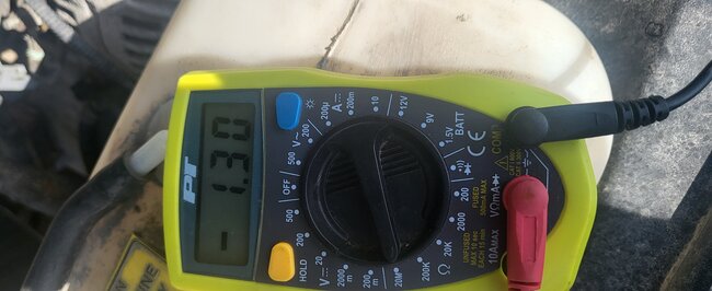
The only real proper way to test the driver right at the PCM is with an LED test light that pulls very low current. And hook the led test light to battery positive and see if the C3 pin 3 at the PCM can ground and light the test light up. I suspect you have high resistance in the TIPM and possibly the wire going to the PCM because of the resistance readings you had at first. One was 1.6M ohms from the ASD relay location and then the other was 1.3M ohms from the TIPM connector, so that's 300k ohms going through the TIPM to its output connector, I think it was C7 pin 11. What's making you suspect a charging system issue now?
Sep 13, 2023 at 5:54 AM
Avatar
LONNIE CARR
  • MEMBER
  • 52 POSTS
Nothing has given me reason to think that.
I'm just grabbing at straws. I Did not start with the overlay, but it does still start if I jump the ASD with the overlay. I'm going out in a little bit to check codes again and see if there's anything I missed. Is there something that could have happened when I hooked up the wiring for the blade?
Sep 13, 2023 at 9:34 AM
Avatar
AL514
  • Experienced Mechanic
  • 5,639 POSTS
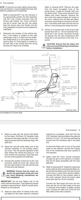
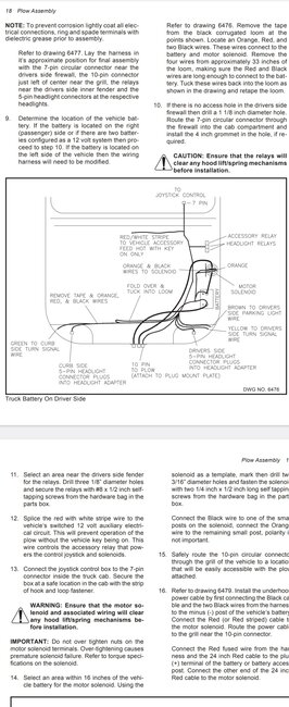
What was involved with installing the plow? And how did you wire it up? Was there a wiring diagram that you followed I could take a look at?
Sep 13, 2023 at 10:53 AM
Avatar
LONNIE CARR
  • MEMBER
  • 52 POSTS
I used a diagram from Hiniker that i got online. I used plug and plays to hook up the lights to the truck side harness and plow control. The red/white wire pushed in with a fuse that gone to ignition switch, and I bolted a solenoid under the hood and hooked it to the battery and ground it to the body.
Sep 13, 2023 at 11:14 AM
Avatar
LONNIE CARR
  • MEMBER
  • 52 POSTS
Hiniker plow 2752.
Sep 13, 2023 at 11:29 AM
Avatar
AL514
  • Experienced Mechanic
  • 5,639 POSTS
Did the starting issue start shortly after the installation? These diagrams are really difficult to see, but what fuse does the red/white wire go to? It's an Accessory feed I see, but is it one of the fuses in the TIPM? These headlamp plow circuits, are they in addition to the vehicles headlamps as well or do they take the place of the original headlamps? I wonder if too much current flow through the TIPM did anything, because it's not just a fuse panel, the Front Control module is built into the TIPM and it's on the vehicle network. But I would still try running a wire over to the PCM and see if that activates the ASD relay.
Sep 13, 2023 at 12:23 PM
Avatar
STRAILER
  • Experienced Mechanic
  • 55,249 POSTS
right?
Sep 14, 2023 at 4:30 AM
Join 2CarPros for free, one of the most advanced car repair communities on the internet. From first-time drivers to seasoned mechanics, everyone is welcome to reply, share details, and get better answers. You can add a temporary image or video first; uploads are limited to 20 MB.
Ask a Free Question
Repair Safety Notice: This information is for general instructional purposes only. Vehicle repair can be dangerous. Verify all information, follow manufacturer service procedures, use proper tools and safety equipment, and consult a qualified repair shop when needed.