Welcome to 2CarPros.
There could be an issue at the data link connector. Since you are getting an error code, then I suggest checking the DLC for power and ground. I am going to attach a flow chart for checking all the terminals on the DLC. You will need to use a multi meter on some tests and a simple test light will work when checking for power. The attached pics correlate with the directions.
Before we get started, here are a few links you may find helpful:
https://www.2carpros.com/articles/how-to-use-a-test-light-circuit-tester
https://www.2carpros.com/articles/how-to-use-a-voltmeter
https://www.2carpros.com/articles/how-to-check-wiring
______________________________________________
2002 Honda Civic DX Sedan L4-1668cc 1.7L SOHC MFI
DLC Circuit Troubleshooting
Vehicle Powertrain Management Computers and Control Systems Data Link Connector Testing and Inspection Component Tests and General Diagnostics DLC Circuit Troubleshooting
DLC CIRCUIT TROUBLESHOOTING
If the ECM/PCM does not communicate with the OBD II scan tool, Honda PGM Tester, or I/M test equipment, do this troubleshooting procedure.
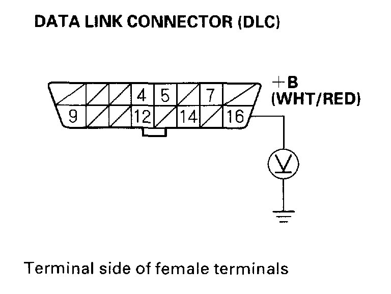
pic 1
1. Measure voltage between DLC terminal No.16 and body ground.
Is there battery voltage?
YES - Go to step 2.
NO - Repair open in the wire between DLC terminal No.16 and the No.9 BACK UP (7.5A) fuse in the under-hood fuse/relay box.
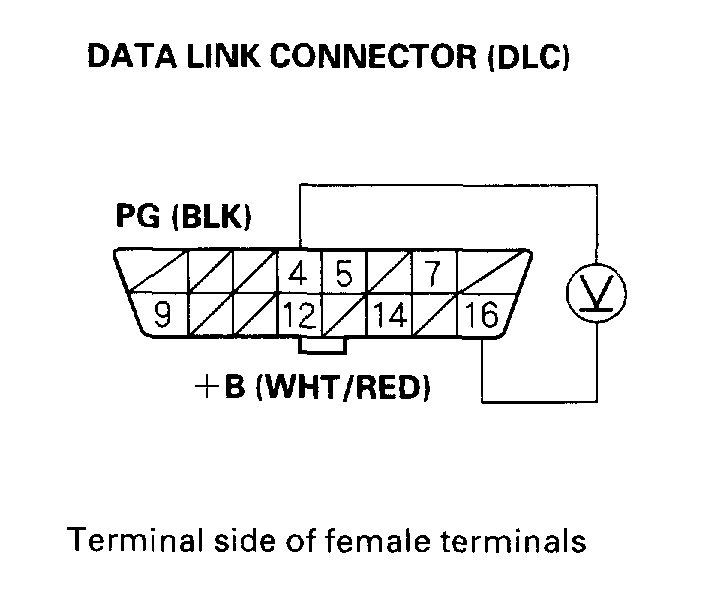
pic 2
2. Measure voltage between DLC terminals No.4 and No.16.
Is there battery voltage?
YES - Go to step 3.
NO - Repair open in the wire between DLC terminal No.4 and body ground.
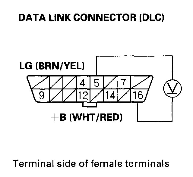
pic 3
3. Measure voltage between DLC terminals No.5 and No.16.
Is there battery voltage?
YES - Go to step 4.
NO - Repair open in the wire between DLC terminal No.5 and ECM/PCM (E3).
4. Turn the ignition switch ON (II).
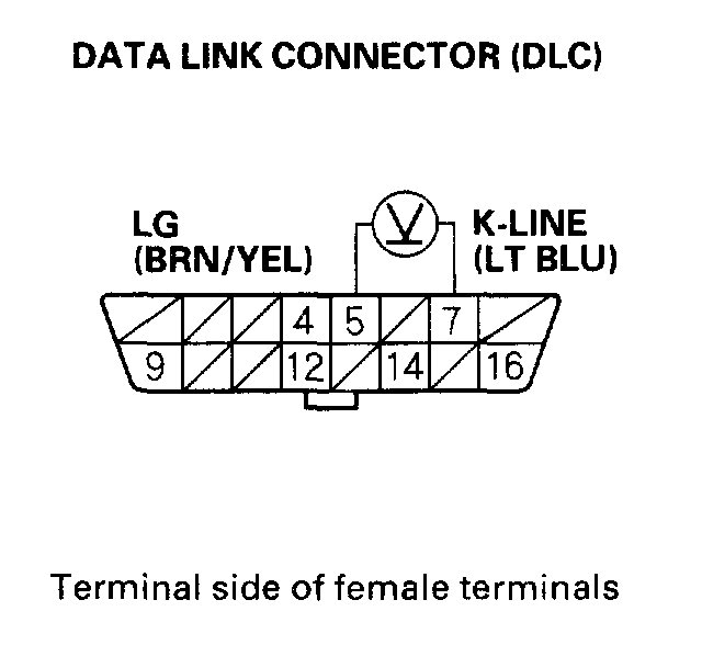
pic 4
5. Measure voltage between DLC terminals No.5 and No.7.
Is there 8.5 V or more?
YES - Go to step 10.
NO - Go to step 6.
6. Turn the ignition switch OFF.
7. Disconnect ECM/PCM connector E (31P). Make sure the OBD II scan tool or Honda PGM Tester is disconnected from the DLC.
pic 5
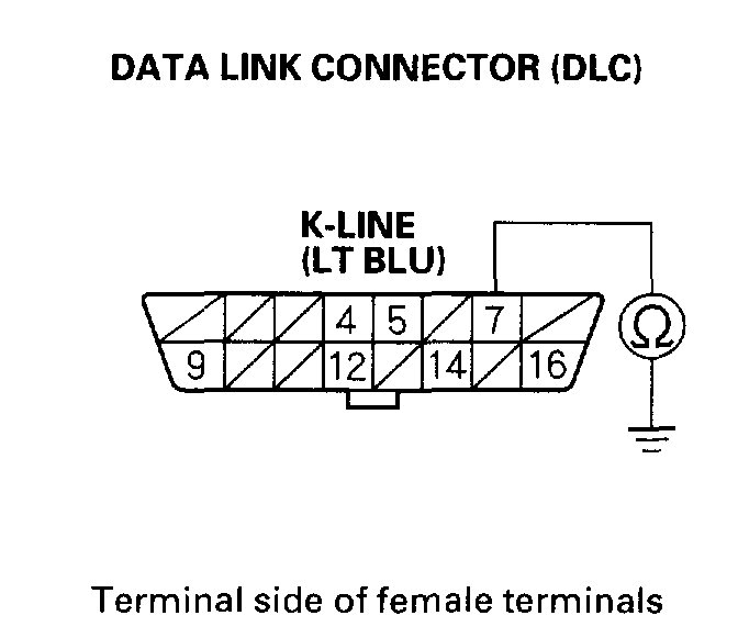
8. Check for continuity between DLC terminal No.7 and body ground.
Is there continuity?
YES - Repair short to ground in the wire between DLC terminal No.7 and the ECM/PCM (E23). After repairing the wire, check the DTC with the OBD II scan tool/Honda PGM Tester and go to the DTC Troubleshooting index. See: A L L Diagnostic Trouble Codes ( DTC ) > Diagnostic Trouble Code Descriptions
NO - Go to step 9.
pic 6
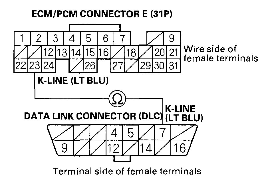
9. Check for continuity between DLC terminal No.7 and ECM/PCM terminal E23.
Is there continuity?
YES - Update the ECM/PCM if it does not have the latest software, or substitute a known-good ECM/PCM, then recheck. If the symptom/indication goes away with a known-good ECM/PCM, replace the original ECM/PCM.
NO - Repair open in the wire between DLC terminal No.7 and the ECM/PCM (E23). After repairing the wire, check the DTC with the OBD II scan tool/Honda PGM Tester and go to the DTC Troubleshooting index. See: A L L Diagnostic Trouble Codes ( DTC ) > Diagnostic Trouble Code Descriptions
10. Turn the ignition switch OFF.
11. Disconnect ECM/PCM connector E (31P). Make sure the OBD II scan tool or Honda PGM Tester is disconnected from the DLC.
12. Turn the ignition switch ON (II).
pic 7
13. Measure voltage between DLC terminals No.5 and No.7.
Is there 0 V?
YES - Update the ECM/PCM if it does not have the latest software, or substitute a known-good ECM/PCM, then recheck. If the symptom/indication goes away with a known-good ECM/PCM, replace the original ECM/PCM.
NO - Repair short to power in the wire between the DLC terminal No.7 and the ECM/PCM (E23). After repairing the wire, check the DTC with the OBD II scan tool/Honda PGM Tester, and go to the DTC Troubleshooting index. See: A L L Diagnostic Trouble Codes ( DTC ) > Diagnostic Trouble Code Descriptions
_________________________
Next is the gear indicator not lighting up when it is in drive. The vehicle has what is called a transmission range sensor which identifies the selected gear. It may be going bad, have a damaged or loose connector, or corrosion may be an issue. Here are the directions for checking it. The last two pics correlate with this test.
________________________
2002 Honda Civic DX Sedan L4-1668cc 1.7L SOHC MFI
Transmission Range Switch Test
Vehicle Powertrain Management Sensors and Switches - Powertrain Management Sensors and Switches - Computers and Control Systems Transmission Position Sensor/Switch Testing and Inspection Component Tests and General Diagnostics Transmission Range Switch Test
TRANSMISSION RANGE SWITCH TEST
Transmission Range Switch Test
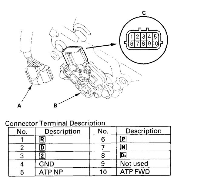
Pic 8
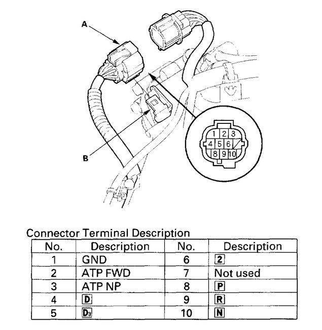
1. Remove the transmission range switch harness connector (A) from the connector bracket (B), then disconnect the connector.
2. Check for continuity between terminals at the harness connector. There should be continuity between the terminals listed for each switch position.
In the P position, between terminals:
No. 1 and No. 3
No. 1 and No. 8
No. 3 and No. 8
In the R position, between terminals:
No. 1 and No. 9
In the N position and between terminals:
No. 1 and No. 3
No. 1 and No. 10
No. 3 and No. 10
In the D position, between terminals:
No. 1 and No. 2
No. 1 and No. 4
No.2 and No.4
In the D3 position, between terminals:
No. 1 and No. 2
No. 1 and No. 5
No.2 and No.5
In the 2 position, between terminals:
No. 1 and No. 6
pic 9
3. If there is no continuity between any terminal, remove the transmission range switch cover, and disconnect the connector (A) at the switch (B).
4. Check for continuity between terminals at the switch connector (c). There should be continuity between the terminals listed for each position.
In the P position, between terminals:
No. 4 and No. 5
No. 4 and No. 6
No. 5 and No. 6
In the R position, between terminals:
No. 1 and No. 4
In the N position, between terminals:
No. 4 and No. 5
No. 4 and No. 7
No.5 and No.7
In the D position, between terminals:
No.2 and No.4
No. 2 and No. 10
No. 4 and No. 10
In the D3 position, between terminals:
No. 4 and No. 8
No. 4 and No. 10
No. 8 and No. 10
In the 2 position, between terminals:
No.3 and No.4
5. If there is no continuity between any terminals, adjust the transmission range switch installation. If the transmission range switch installation is OK, replace the switch.
6. If the transmission range switch continuity check was OK, replace the faulty transmission range switch harness.
__________________________________
Let me know if this helps or if you have other questions.
Take care,
Joe
Images (Click to make bigger)
Saturday, August 8th, 2020 AT 11:11 AM
(Merged)
