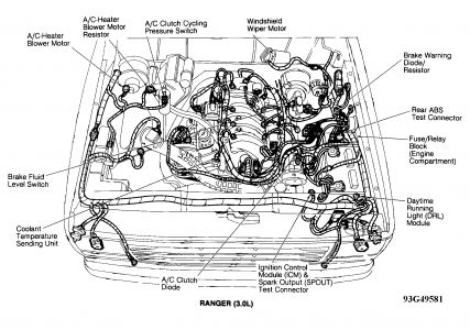
Nope, The ICM controls it all when it comes to the spark plugs. It determines which plug and when to fire. A bad relay would knock out the entire module so you have no spark at all. Same if it was a bad crankshaft or camshaft sensor, they would shut off all spark.
The wiring diagram is the modules connections. Notice the pins saying coils 1-4? Those are what tells which coil to fire. Check them over to be sure there is no corrosion or bad connection for the one labeled coil 1 (pin 11) That would be the only spot other than a bad coil, plug wires or plugs that would stop spark on cylinder 1.
Here is the theory of operation for your DIS system.
The Distributorless Ignition System (DIS) module performs the following important functions:
- provides a ground for the ignition system through two of the module mounting screws
- selects which ignition coil within the coil pack to fire
- contains solid-state electronic switches that control current to the coil primary circuits within each coil pack
- limit current flow in each coil primary circuit to a maximum of 5.5 amps
- generate the Ignition Diagnostic Monitor (IDM) signal; this provides diagnostic information about the ignition system to the Powertrain Control Module (PCM).
- provide Failure Mode Effects Management (FMEM) operation.
The second item in that list is the important one in your case. The module selects which coil to fire and when based on the signals it gets.
CONSTRUCTION
The DIS ignition module is a thick film integrated design. The module contains a ceramic substrate thick film assembly and four output drivers mounted on a metal base plate and potted in a plastic housing.
OPERATION
The DIS ignition module receives the PIP (Profile Ignition Pickup) and CID (Cylinder Identification Device) signals from the crankshaft sensor and Spark Output (SPOUT) signal from the PCM. During normal operation, PIP is sent to the PCM from the crankshaft timing sensor and provides base timing and RPM information. The CID signal provides the DIS ignition module with the information required to synchronize the ignition coils so that they are fired in proper sequence. The SPOUT signal contains optimum spark timing and dwell time information. Spark angle is determined by the rising edge of SPOUT, while the falling edge of SPOUT controls the coil current "ON" or "DWELL" time. The dwell time is controlled or varied by varying the duty cycle of the SPOUT signal.
Image (Click to make bigger)
Wednesday, July 29th, 2020 AT 11:45 AM
(Merged)

