If it was my car I would go for crank sensor, at the end of the day it is responsible for generating the spark output to the ECA. of course i would have the vehicle diagnosed first.
Crankshaft Sensor:
A dual Hall Effect crankshaft sensor, mounted at crankshaft pulley, is used on 2.3L dual-plug distributor-less ignition system (DIS). Sensor signals are generated when two trigger wheels, mounted on pulley assembly, pass through air gap of two Hall Effect switches. One switch produces a profile ignition pick-up (PIP) signal, monitored by DIS ignition module to provide rpm signal to ECA. The second switch produces cylinder Identification (CID) signal, used by DIS ignition module to identify which coil pack to trigger. If CID signal is not present, vehicle will be hard to start.
Profile ignition pick-up (PIP):
On 2.3L DIS ignition systems, modulated PIP and CID signals are produced by dual Hall Effect crankshaft sensor and monitored by DIS ignition module. See crankshaft sensor under input devices. Ignition module relays the PIP signal to ECA, which uses it as an RPM reference to determine timing adjustments.
ECA timing control returns to ignition module in form of a spark output (SPOUT) signal. The leading edge of SPOUT signal fires coil, and trailing edge controls dwell on-time.
On 4.0L EDIS ignition systems, PIP signal is generated by variable reluctance sensor (VRS), located near crankshaft pulley. The VRS is a permanent magnet (PM) generator, which produces an AC voltage signal which increases with rpm. The EDIS ignition module monitors this signal, passes this information on to ECA and modifies coil triggering signal based upon a spark angle word (SAW) signal sent from ECA.
On distributor-type ignition systems, PIP signal is provided by a twelve volt reference from ignition module to Hall Effect switch, inside distributor. This reference voltage is modulated by window/shutter Hall Effect switch. Monitored reference is pulled low when shutter blade is out of Hall Effect switch window.
When shutter blade enters window, twelve volt reference returns, and TFI ignition module sends PIP signal to ECA. ECA uses the PIP signal as an rpm reference to calculate timing adjustments. ECA timing control returns to ignition module in form of a Spark Output (SPOUT) signal.
Electronic control assembly (ECA):
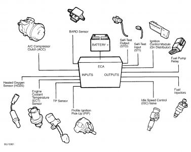
During system operation, ECA transmits electrical reference signals to engine sensors and analyzes return signals to determine engine operating conditions. See figure one. If a sensor or actuator fails, ECA initiates an alternative strategy, allowing vehicle to maintain driveability. This strategy is called failure mode effects management (FMEM).
The check engine light will illuminate and remain on whenever FMEM is in operation. The ECA, overriding failed component with a FMEM substitute operation value, continues to monitor failed sensor. Should signals from faulty sensor return to within operational limits, ECA will cancel FMEM and resume control based on sensor signals.
Explorer and Ranger, behind right kick panel.

Thursday, December 4th, 2008 AT 10:51 AM


