Engine cranks but will not start

Tiny
AL514
  • MECHANIC
  • 4,677 POSTS
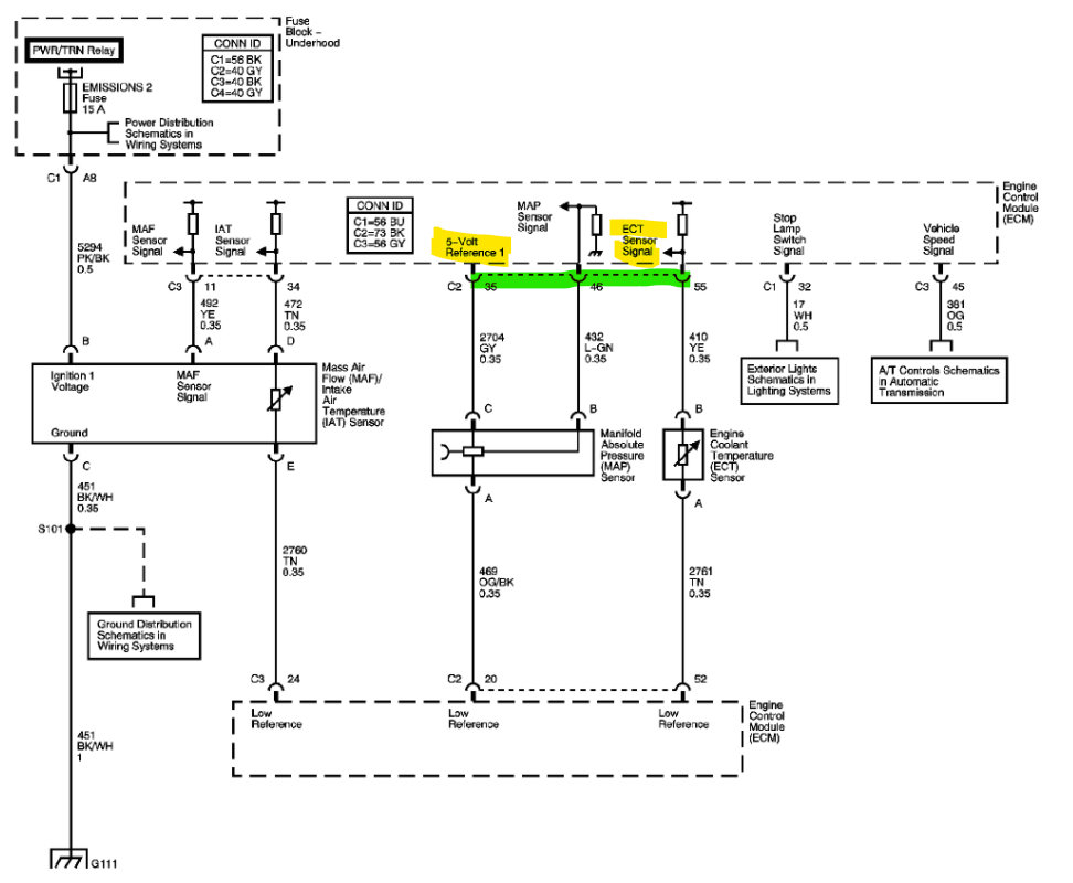
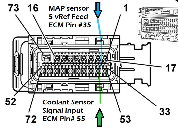
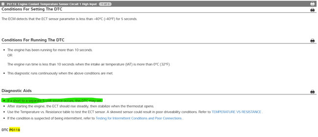
Okay, after going through everything and looking up some code setting criteria, I have a theory as to what might be happening. This is just hypothesis, but I found that the Coolant Sensor code P0118 can be set if the sensor is shorted to a separate/different 5-v Ref wire. And I thought it was strange that you were getting 0/Ground voltage signal on ECM Pin #35 but still getting 4.9 volts at the Map sensor (pin #35 is the Map sensors 5vRef).

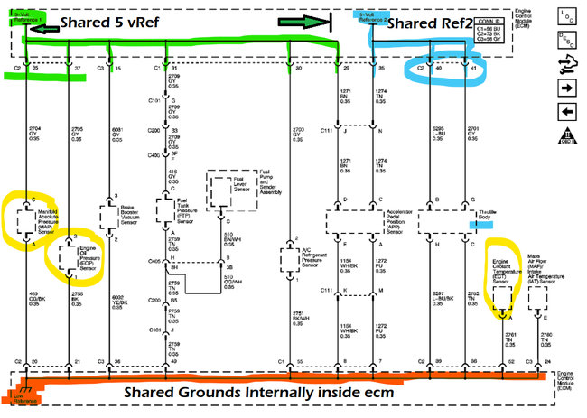
So, then I looked at the Chevrolet OEM diagrams and found that the Coolant Sensor signal input wire to the ECM and the MAP sensors 5v Ref feed wire pins at the ECM are right next to each other. I will put the diagrams below. I think the Map sensor 5vRef is shorting to the Coolant sensors input Signal wire at the ECM connector, there might be a bent pin there or some corrosion, but it makes sense that the Map sensors signal would be low, and the Coolant sensors signal would be High input just like the first 2 codes you're getting.

I'm not sure if you unplugged the ECM C2 connector or not, but I think this is what's happening, after seeing where the pin locations were and that the coolant sensor code can set due to a "different Reference voltage being shorted to it", this would explain why you're not reading anything at ECM pins 35 and 37, I just wondering why you're not getting any other codes, unless it's because the Map sensors Ref V is first in line and being pulled down first, therefore messing with the ECM.

Watch I'll probably be wrong after all that, but do a real good inspection of that C2 ECM connector and the pins in the ECM side of the connection.

Try the suggestions about the Oil Pressure sensor and MAP sensor also in the previous post. Just to be sure of what's happening here. I want to be sure we know what we're dealing with. A clue too was the new codes you got, something got messed with when the wiring harness was moved around for testing.
Was this
answer
helpful?
Yes
No
Monday, February 14th, 2022 AT 6:55 PM
Tiny
RONALD DEVOLD
  • MEMBER
  • 104 POSTS
I don't know how but the 5v reference is reading at the sensors and ECM. I unplugged them and there was voltage at both sensors and ECM. And also, once I plugged them back one at a time.
Was this
answer
helpful?
Yes
No
Tuesday, February 15th, 2022 AT 6:43 AM
Tiny
AL514
  • MECHANIC
  • 4,677 POSTS
It's because either you've moved the harness away from an area it was shorting out on, or one of those sensors has a pin fitment issue. Does the vehicle start now? And did you inspect the ECM connectors?
Whatever wires you've moved around during all this, that is your problem area with the harness, there has to be a corroded connection or loose pin fitment going on somewhere where your hands have been. This is why we don't move wiring harnesses around too much during testing, because you can accidentally fix the problem and not know where it actually is.
Was this
answer
helpful?
Yes
No
Tuesday, February 15th, 2022 AT 10:44 AM
Tiny
RONALD DEVOLD
  • MEMBER
  • 104 POSTS
Okay. I will double check all wires and see if I can mount the ECU back and still back probe the wires. And the vehicle still will not start.
Was this
answer
helpful?
Yes
No
Tuesday, February 15th, 2022 AT 11:08 AM
Tiny
AL514
  • MECHANIC
  • 4,677 POSTS
It might be a pin fitment issue right at the ECM, if you're moving that ECM around to get at those connectors so you can back probe them, look at the pins themselves, even a slight bend on one of them can short it to another pin, I mean look at where they put the ECM, it's not in a protected place from moisture or anything else, With moving it around like that something happened. Also did you see if you have 12 volts at the crank sensor? If it's still a crank, no start, and you have a crank sensor code. Go right for the sensor, check that it has 12-volt feed, a good ground, check the connector on that sensor too, I think you're right in the area of getting this thing figured out. Those reference voltages needed to be restored and it needs a crank signal to start and fire the coils and injectors.
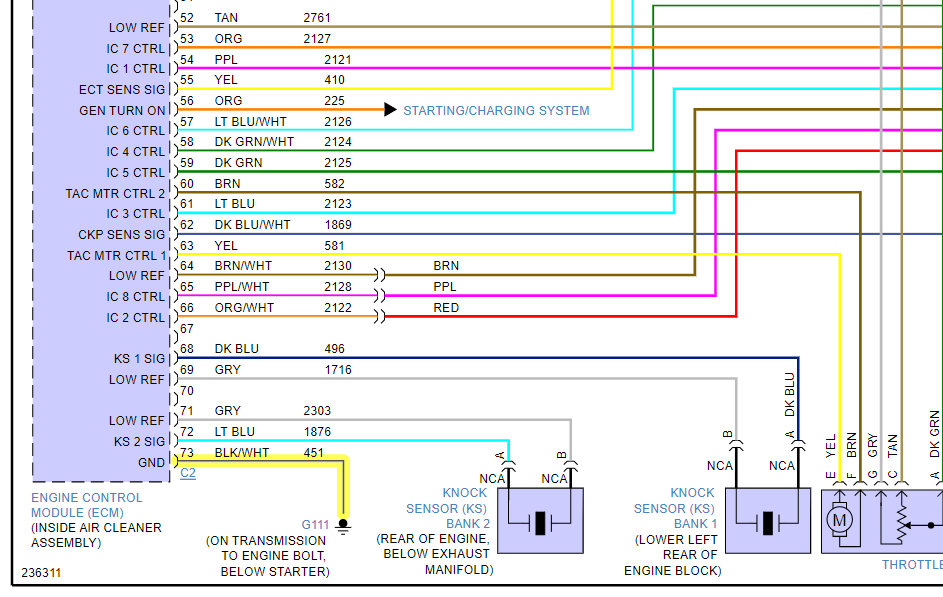
Look for basic stuff, don't over think it. You're really close, granted you may have a bad crank sensor, but this car was a no crank to begin with, then no 5-v Ref. Then 3 new codes, then 5-v Ref back again, this has a wiring issue. I'm going to pull up the diagrams for the ECM Grounds as well. So, we know where those are.

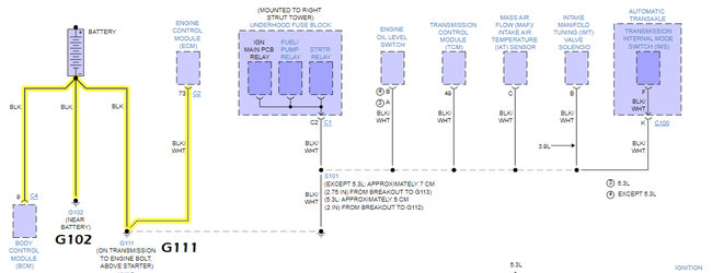
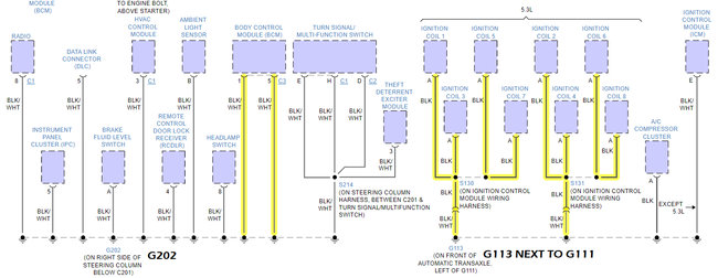
This ECM only has one Ground as well, and the Ignition Coils ground right next to the ECM ground. Diagrams below.
Was this
answer
helpful?
Yes
No
Tuesday, February 15th, 2022 AT 11:18 AM
Tiny
RONALD DEVOLD
  • MEMBER
  • 104 POSTS
So, I know it's been some time since last touched basis, but finally I have the time to jump back on my project. So here is what I have now:
P0122-Throttle Position Sensor 1 Circuit Low Voltage
P0223-Throttle Position Sensor 2 Circuit High Voltage
P0315-Crankshaft Position System Variation Not Learned
P0335-Crankshaft Position Sensor †A’ Circuit Malfunction
I will focus on the Crankshaft codes. The 3 wires going to the sensor are LT-GN(12v REF), D-BLU/WHT(CKP SENSOR SIGNAL) and YE/BK(Low Reference)
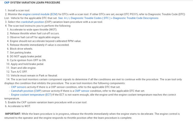
With key on I am getting the 12v REF, THE LOW REFERENCE, but I'm only getting.09-1.9v on the signal wire while cranking. I don't know what reading I should be getting on the signal wire. Another thing that has me scratching my head is, how can I perform a crank sensor relearn with an engine that is not running?
Was this
answer
helpful?
Yes
No
Friday, June 24th, 2022 AT 9:55 AM
Tiny
AL514
  • MECHANIC
  • 4,677 POSTS
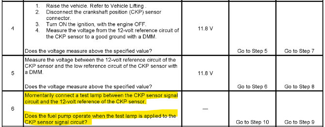
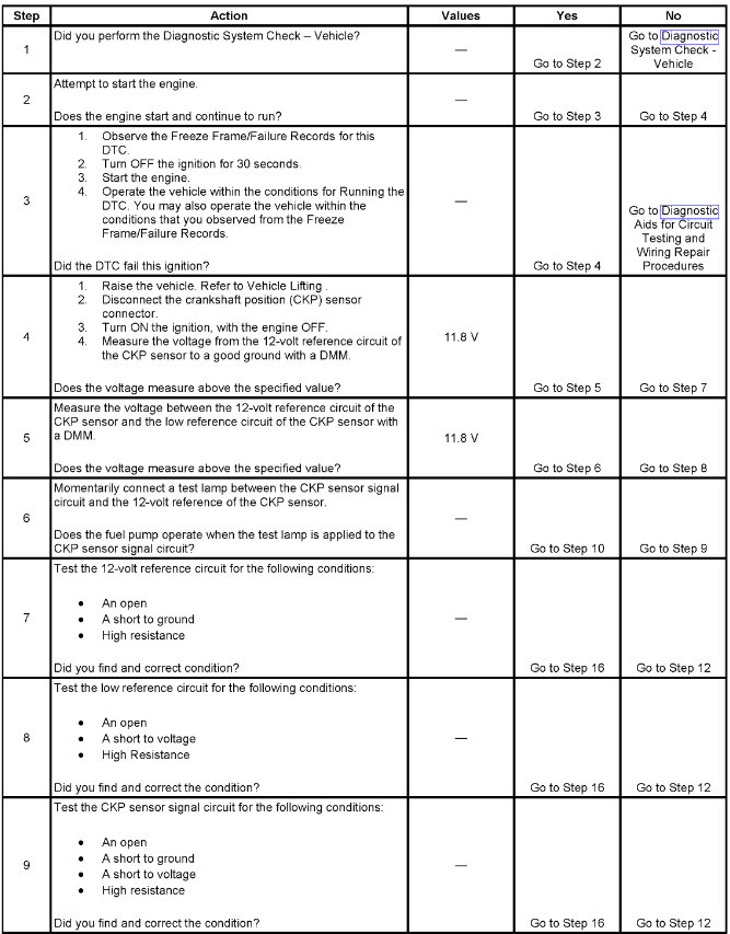
Okay, since you have 12-volts at the sensor, that's good, but what they want you to do is even if you have 12-volts across the power feed and low ref(ground), they want you to do a semi load test to verify both power and ground circuits are actually okay. This is a pretty quick test, they want you to connect a regular automotive 12-volt test light across the 12-volt feed and sensor signal wire momentarily (so not very long), and the Fuel pump should come on, so only do this test long enough to hear the pump or watch your fuel pressure gauge jump up. This will simulate the engine running and verify your power and ground for the sensor. Once you do this test, and I'm going to assume the fuel pump will come on.
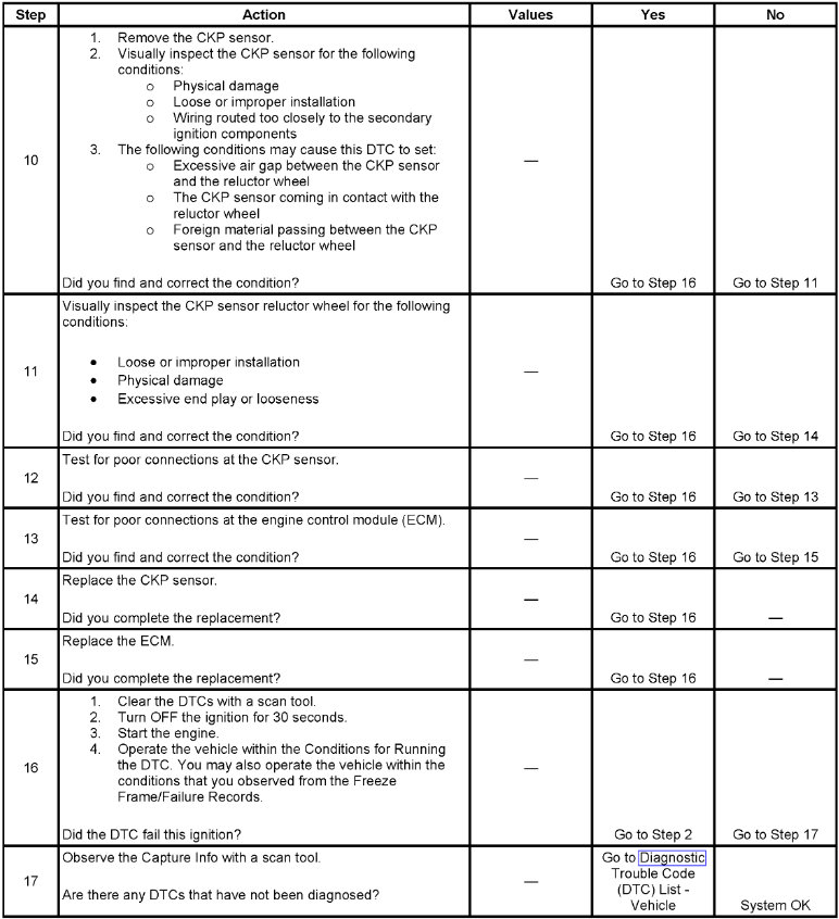
After that it says to inspect the crankshaft sensor for 1. Any wiring routed too close to Secondary Ignition sources (coils, plugs, etc.), Check that the gap at the sensor is ok and that there is nothing wrong with the trigger wheel or anything obstructing the sensor (dirt, oil, etc). Anything that may affect the signal. I know that if there is an excessive gap at the sensor it can throw off the reading. If you pull out the crank sensor and the end of it is all scratched up or has been rubbing on anything you should be able to see it pretty easy. You are most likely going to be changing the sensor anyway. It looks like it's just one bolt to hold it into the engine block. The new sensors usually come with a sticker type piece on the front of the sensor where it picks up its signal, which is there to set the gap to the trigger wheel. This one doesn't look adjustable, but just so you know not to remove that sticker.

Not sure where you are testing the sensor from, it looks like it's under the exhaust manifold, it says to remove the manifold to replace the sensor, but I would see if you can get to it without having to do that. If you are testing it from a different location, then inspection of its connector and the wiring down to it is needed. I will get all the relearn info for you, as well as the other TPS code info. The relearn might be hindered if there are other codes stored that have to do with engine controls as well. I'll post the rest as I get it together here real quick.

And are you doing the relearn with a scan tool?
Was this
answer
helpful?
Yes
No
Friday, June 24th, 2022 AT 11:16 AM
Tiny
AL514
  • MECHANIC
  • 4,677 POSTS
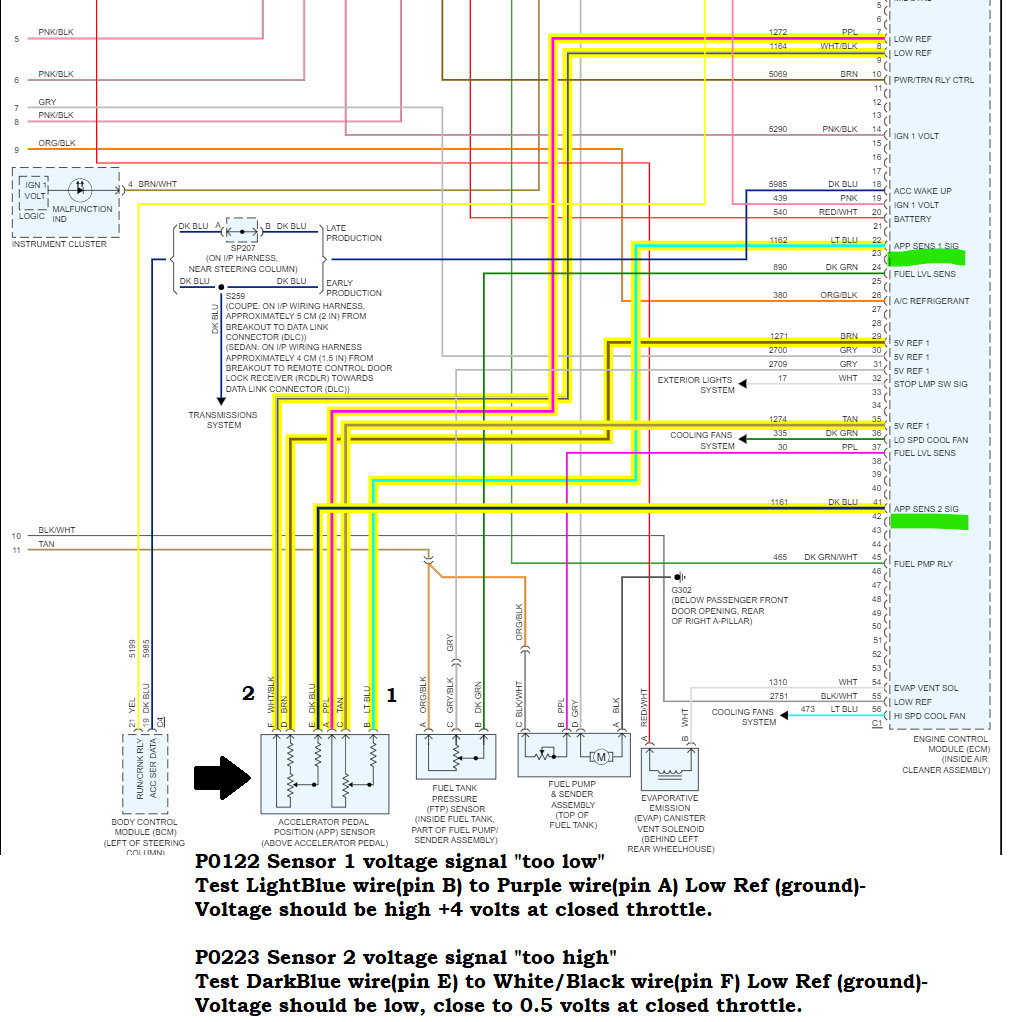
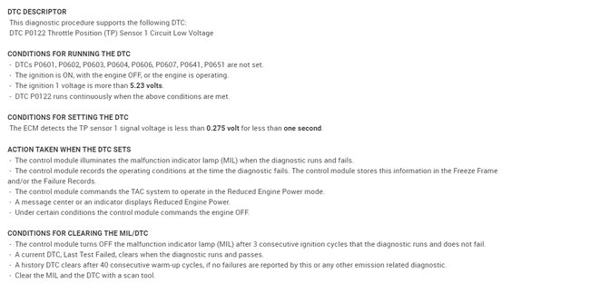
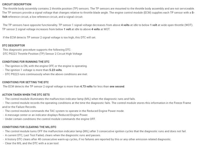
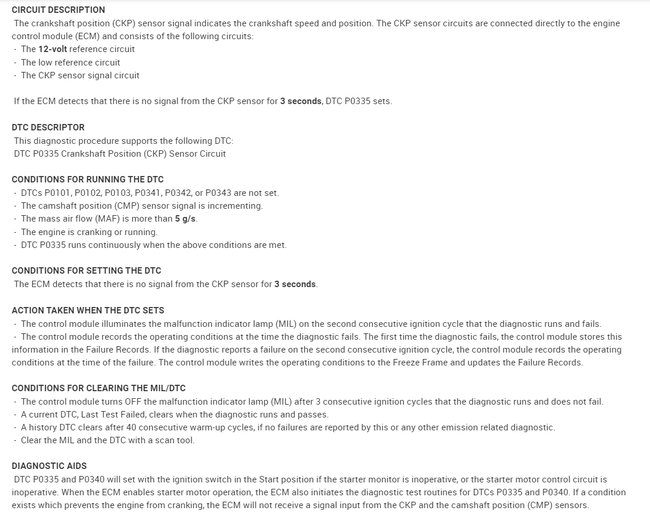
The first three diagrams are for the TPS codes and testing. Pages 4 to 6 are for the Crankshaft Position sensor code and testing. The last two pages are the Crankshaft Position sensor Variation Relearn Procedure. Make sure you clear all codes before doing any re-learn procedure. That includes taking care of the APP (TPS) sensor on the gas pedal. It sounds like it might have shorted out internally. It has two Throttle Position Sensors built into one. So, there's two 5-volt reference wires, two signal wires, and two grounds going to the ECM. Both the signals go opposite each other with throttle (pedal) movement. So, one goes around 4-volts down and the other around 0.5-volts up.

https://www.2carpros.com/articles/crankshaft-angle-sensor-replacement
Was this
answer
helpful?
Yes
No
Friday, June 24th, 2022 AT 1:35 PM
Tiny
RONALD DEVOLD
  • MEMBER
  • 104 POSTS
I replaced the crank sensor and still getting the same results. I am unable to retrieve the other feed, so I think I am at a dead end with this issue.
Was this
answer
helpful?
Yes
No
Saturday, July 2nd, 2022 AT 10:16 AM
Tiny
AL514
  • MECHANIC
  • 4,677 POSTS
You're still only getting around two volts from the crank shaft signal wire? Or are you getting a different voltage reading now? If the reading is still that low. It's probably something to do with the trigger wheel for the crankshaft sensor. If the sensor is not close enough to the trigger wheel it won't send the full voltage signal because the magnetic field is not being interrupted enough by the trigger wheel. The trigger wheel on this vehicle has 24 teeth, as each tooth passes the crankshafts sensors magnets it creates a pulse to the ECM. There could be a problem with the trigger wheel.
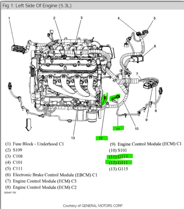
You should check to see that the crankshaft has not become magnetized. Shafts can become magnetized when there are main Ground wires that are in the wrong place. For example, if a ground has been moved to the engine block from some other location. The Ground location G111 should go from the Transmission to Engine just above the Starter motor. If a main ground like that has been moved to a place where it should not be, the current flow from the Starter Motor will find new ground path and it can end up magnetizing the Crankshaft, a Camshaft, etc. When that happens sensors like this won't read correctly. So, I would take a small screwdriver that you know is not magnetic, and just touch the end of the Crankshaft and see if it has become magnetized. This is why grounds are put in specific locations. But check to see if that may be what's happening. See if the small screwdriver sticks to the end of the crankshaft. Also, if you notice any ground wires besides the one that should be about two inches from the Starter motor.
This usually happens when a ground near the Starter has been moved because the Starter has such a huge current draw, much more than any other component. I'll try to find a video on this so you can get a better idea of this situation.

Watch this whole video, this is all about shafts getting magnetized. The vehicle in this video is having an issue with the crankshaft signal not being strong enough.
If you're getting some other voltage reading higher than the 1.9volts you were getting let me know.

https://www.youtube.com/watch?v=2eApL4UPT4Q
Was this
answer
helpful?
Yes
No
Saturday, July 2nd, 2022 AT 2:32 PM

Please login or register to post a reply.

Related Engine Not Running Content

Sponsored links