Troubleshoot wiring harness 68236867AD repair?

Tiny
TIMOTHY HUFF
  • MEMBER
  • 2015 CHRYSLER TOWN AND COUNTRY
  • 3.6L
  • 6 CYL
  • 2WD
  • AUTOMATIC
  • 195,000 MILES
Vehicle tries to start, barely. Engine turns over catches a little bit then just turns over and over. Current 7 codes from my Inova 5610:
P1628 sensor reference voltage 2 erratic.
P0600 serial communication link.
P0340 camshaft position sensor circuit bank 1 sensor 1
P0335 crankshaft position sensor circuit
P0345 camshaft position sensor circuit bank 2 sensor 1
P0365 camshaft position sensor circuit bank 1 sensor 2
P0390 camshaft position sensor circuit bank 2 sensor 2

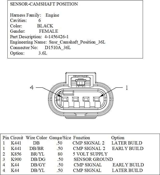
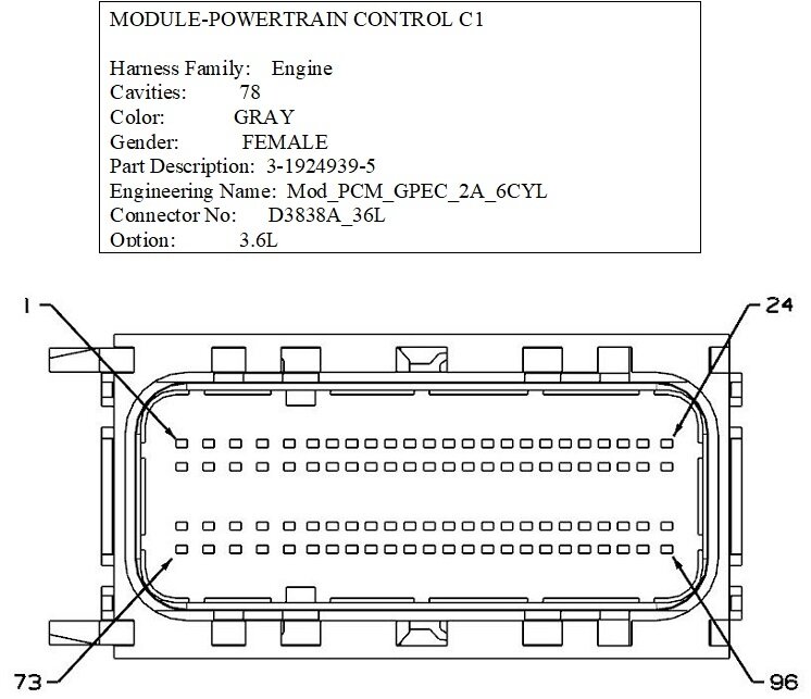
I'm trying to verify the condition of wiring harness #68236867AD Specifically the camshaft and crankshaft position circuits. I am hoping you can provide wiring diagrams connector diagrams pinouts and possible voltage and resistance at those connectors. I am an electrician and I know how to use a tester. I also know how to fix wires. I would gladly work with you completely on this repair seeing as information has been hard to find. I'm usually very good with Google.
Saturday, January 20th, 2024 AT 1:13 PM

60 Replies

Tiny
TIMOTHY HUFF
  • MEMBER
  • 36 POSTS
I'm looking for a way to do a simple continuity test. I will unplug the PCM connector, I will unplug the camshaft position sensor, and if I know the pin numbers on both connectors, I can check its continuity. I could also check to see if that wire has continuity to ground. Or continuity to each other of the wires at the camshaft position sensor.
Was this
answer
helpful?
Yes
No
Saturday, January 20th, 2024 AT 1:59 PM
Tiny
CARADIODOC
  • MECHANIC
  • 33,883 POSTS
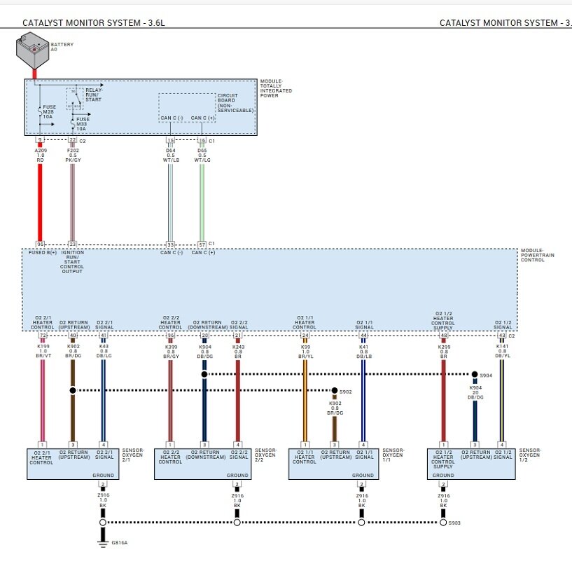
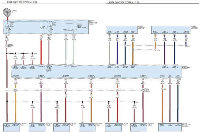
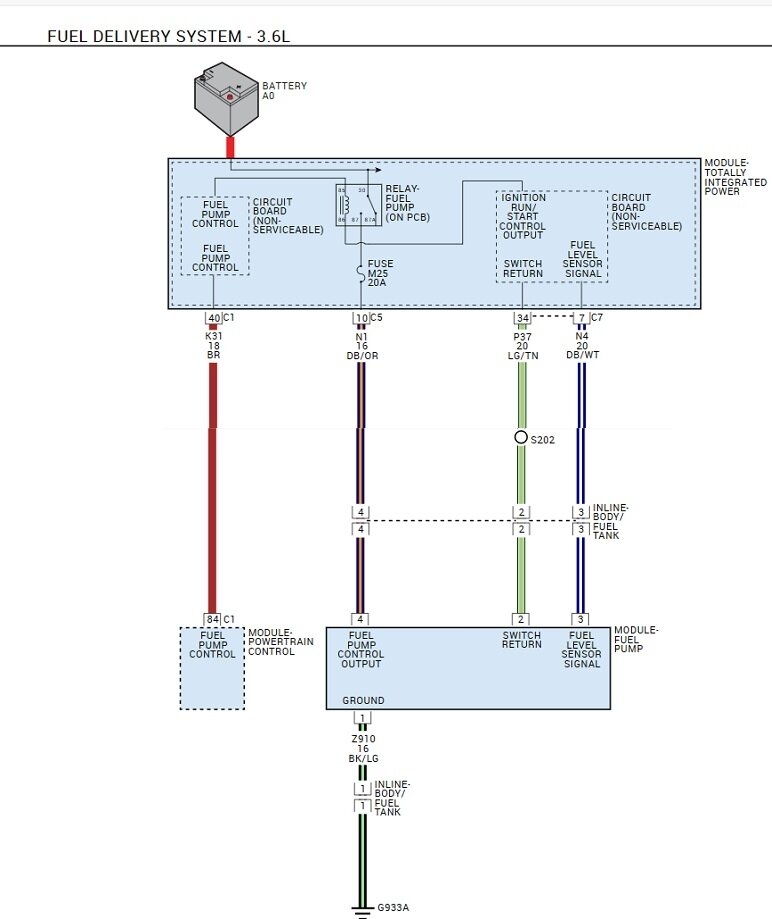
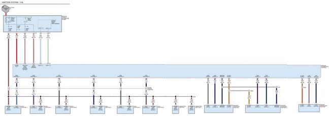
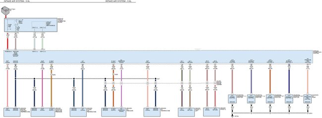
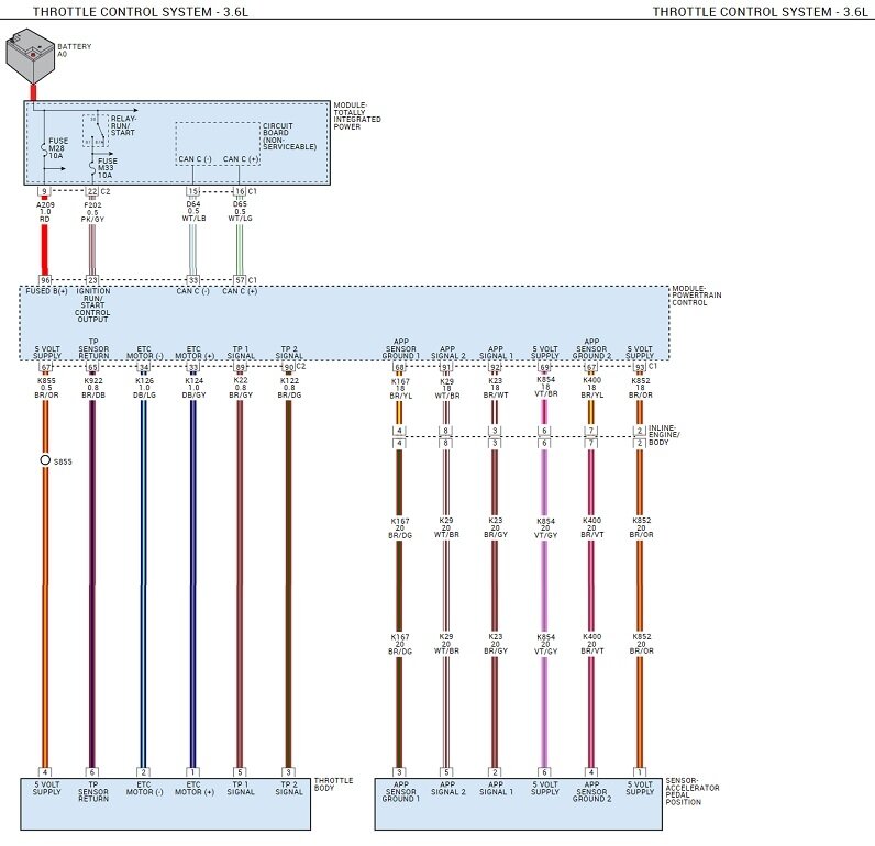
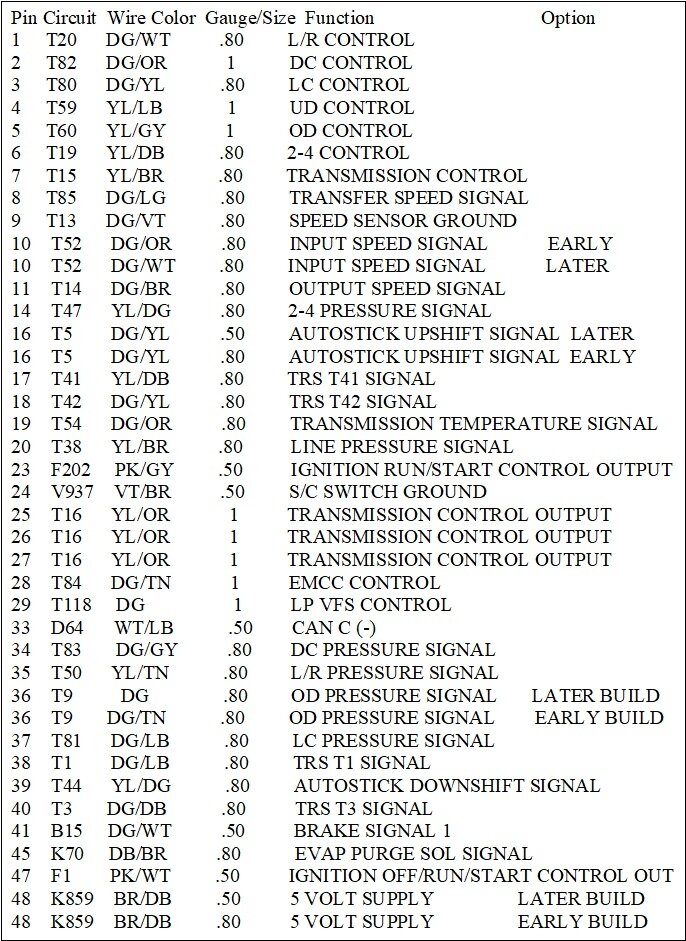
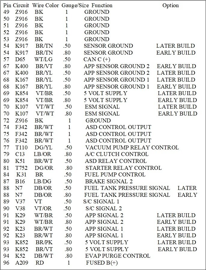
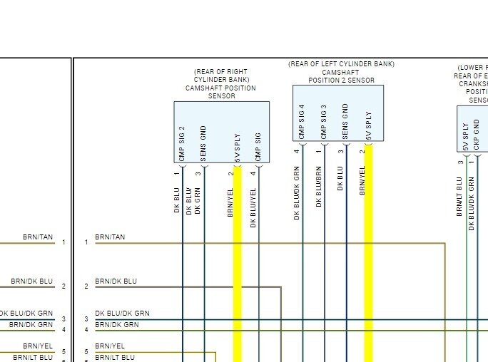
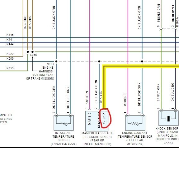
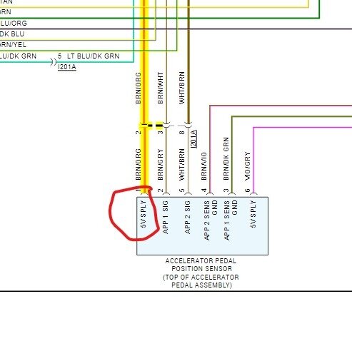
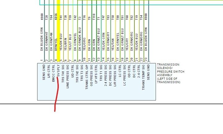
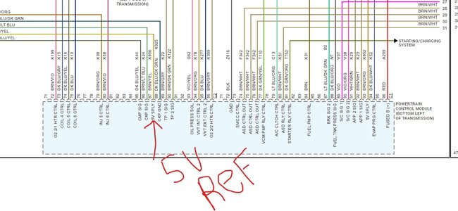
Sorry to take so long. The only diagrams I have access to are rather miserable compared to Chrysler's diagrams. It takes a long time to format them for uploading. These seven are for Powertrain Management. The last four are for your connectors. If you give me some time, I can do the same thing for the fault code diagnostic steps.
Was this
answer
helpful?
Yes
No
+1
Saturday, January 20th, 2024 AT 5:55 PM
Tiny
STEVE W.
  • MECHANIC
  • 13,496 POSTS
With all of those codes I don't think you need to do all that. It sounds like you have lost the 5-volt reference voltage to the sensors. It's the one thing they all share. The attached are the sensors that get power from pin 87 on the powertrain control module. I would start at the MAP sensor on the rear of the intake manifold. With the key on there should be 5 volts at pin 3 the Brown w yellow wire. I would suggest using a needle to poke through the seal on the connector and test for 5 volts that way, I suspect you will find no power. Unplug the sensor, have 5 volts now? MAP is shorted, still nothing, keep the meter in place, unplug the cam sensors one at a time, when you see 5 volts return, you found the shorted sensor. Replace it and verify the 5 volts is back. Now in the event you unplug them all and still have no 5 volts you can go to the PCM and back probe at pin 87 and see if there is voltage there. If yes, then that wire is likely broken or shorted in the harness that feeds the other sensors.
Was this
answer
helpful?
Yes
No
+1
Saturday, January 20th, 2024 AT 6:06 PM
Tiny
TIMOTHY HUFF
  • MEMBER
  • 36 POSTS
Please take your time.
Was this
answer
helpful?
Yes
No
Saturday, January 20th, 2024 AT 6:13 PM
Tiny
TIMOTHY HUFF
  • MEMBER
  • 36 POSTS
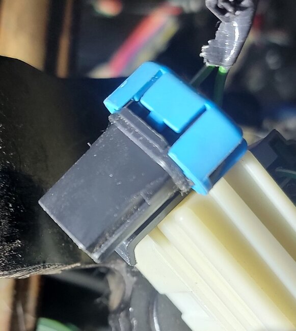
Found this 2-wire connector "dangling" over my gas pedal, on the brake pedal side. Cannot find a connector for it. Wire colors both greenish in color, one with possible blue tracer. These wires look to be intentionally twisted together? It can't be this easy! Lmk Thank you!
Was this
answer
helpful?
Yes
No
Saturday, January 20th, 2024 AT 6:40 PM
Tiny
STEVE W.
  • MECHANIC
  • 13,496 POSTS
Doubt that is it, that looks like the optional connector for the adjustable pedal motor. That would be a 2 wire with a light green with blue and one light green with yellow.
Was this
answer
helpful?
Yes
No
+1
Saturday, January 20th, 2024 AT 6:51 PM
Tiny
CARADIODOC
  • MECHANIC
  • 33,883 POSTS
Dandy answer, brother Steve, dandy answer. I have one comment of value though. I can't say for sure on something this new, but on the older Chryslers, when the 5-volt supply became shorted, the computer shut it down to protect it. Once you unplugged or fixed whatever was causing the short, the ignition switch had to be turned off, then back on to reset that power supply. It didn't come back on its own.

Let me know when you need more of my wondrous wisdom.
Was this
answer
helpful?
Yes
No
+1
Saturday, January 20th, 2024 AT 7:02 PM
Tiny
TIMOTHY HUFF
  • MEMBER
  • 36 POSTS
Hi guys thank you for your help, I'm probably going out tomorrow morning and taking some voltage measurements. The only thing I need to know is, when testing for 5vdc at the camshaft connector, is that to Chassis ground, or the sensor ground pin in the camshaft connector?
Was this
answer
helpful?
Yes
No
Sunday, January 21st, 2024 AT 11:43 AM
Tiny
STEVE W.
  • MECHANIC
  • 13,496 POSTS
Both will work if you know the ground pin on the sensor is okay.
Was this
answer
helpful?
Yes
No
+1
Sunday, January 21st, 2024 AT 10:20 PM
Tiny
TIMOTHY HUFF
  • MEMBER
  • 36 POSTS
What's next after I do have 5 volts and all the correct pens?
Was this
answer
helpful?
Yes
No
Monday, January 22nd, 2024 AT 11:31 AM
Tiny
TIMOTHY HUFF
  • MEMBER
  • 36 POSTS
I could find nothing wrong with the suggestions that you guys offered. Help.
Was this
answer
helpful?
Yes
No
Monday, January 22nd, 2024 AT 12:54 PM
Tiny
TIMOTHY HUFF
  • MEMBER
  • 36 POSTS
Although the idling very rough with lots and lots of white smoke. It'll for approximately 15 seconds I had to use the gas pedal to get it going.
Was this
answer
helpful?
Yes
No
+1
Monday, January 22nd, 2024 AT 12:55 PM
Tiny
TIMOTHY HUFF
  • MEMBER
  • 36 POSTS
Both cam sensors crankshaft sensor and MAP sensor have been replaced!
Was this
answer
helpful?
Yes
No
+1
Monday, January 22nd, 2024 AT 12:56 PM
Tiny
TIMOTHY HUFF
  • MEMBER
  • 36 POSTS
And maybe we should wonder if that two wire connector dangling over the gas pedal actually does have something to do with this.
Was this
answer
helpful?
Yes
No
+1
Monday, January 22nd, 2024 AT 12:57 PM
Tiny
STEVE W.
  • MECHANIC
  • 13,496 POSTS
That connector is nothing to do with this issue. It is the power connection for the electrically adjusted brake and throttle pedals. It goes up to the switch that allows the pedals to be adjusted like a seat is adjusted if you have that option. Does nothing else with the rest of the vehicle.
You say it's a lot of white smoke and that it will start if you hold the throttle open? That sounds like the injectors are firing wide open but the fuel is so rich it's flooding it until air gets in there to lean the mix out and it can start. If you clear those codes do they come right back? Do you have access to an oscilloscope? That would let you look at the actual signal waveform and see what the PCM is getting for a timing signal.
Was this
answer
helpful?
Yes
No
+1
Monday, January 22nd, 2024 AT 4:32 PM
Tiny
CARADIODOC
  • MECHANIC
  • 33,883 POSTS
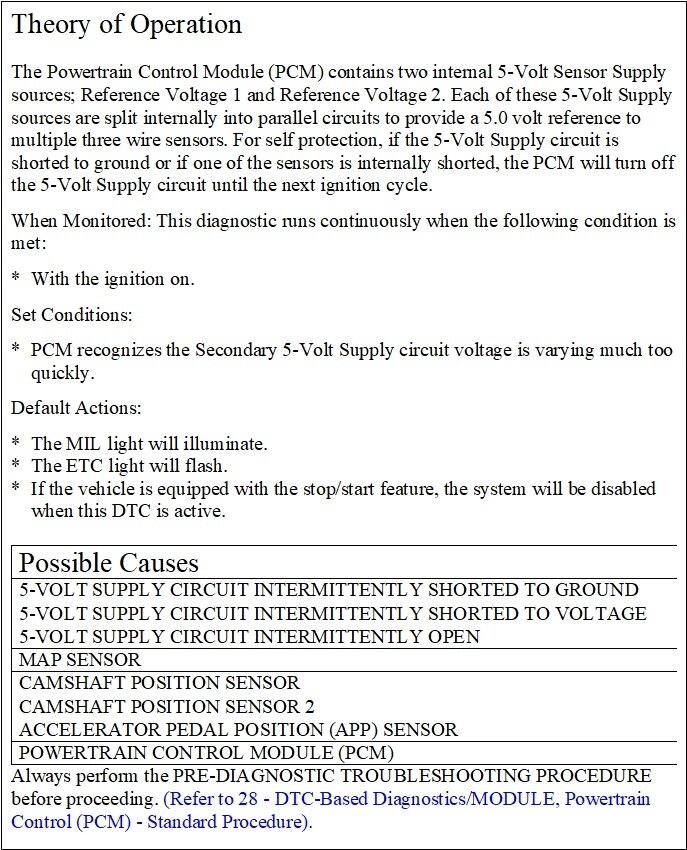
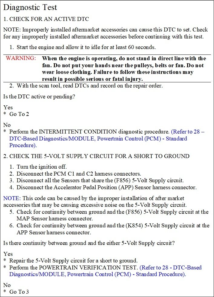
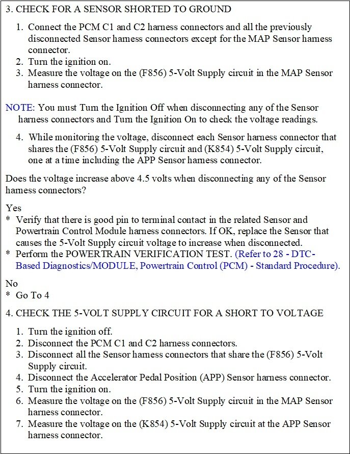
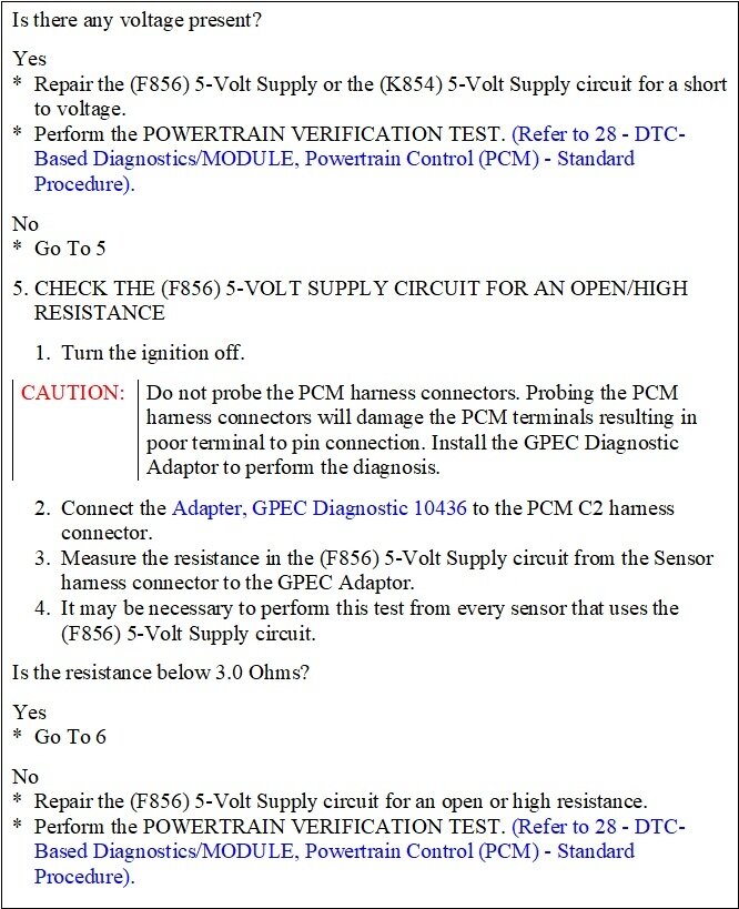
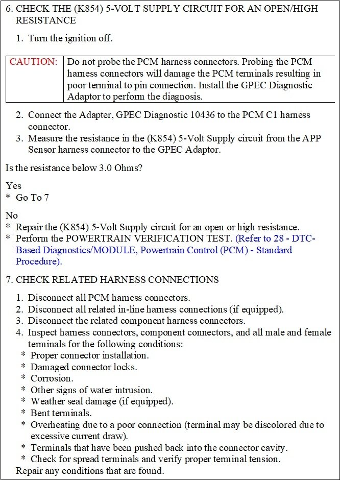
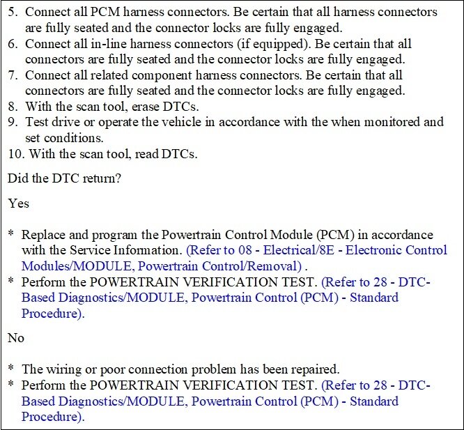
I'm a little behind, but it seems we're looking at the 5-volt supply, (there's two here), as a possible suspect, so I copied and formatted the diagnostic chart for code P1628. Look through this and see if it helps.
Was this
answer
helpful?
Yes
No
+1
Monday, January 22nd, 2024 AT 5:18 PM
Tiny
TIMOTHY HUFF
  • MEMBER
  • 36 POSTS
Alright guys let's all get on the same page, As of 9:00 PM Eastern Standard Time Monday January 22nd 2024, With a multimeter I was able to Verify the 5 volt reference voltage at the Map and Cam sensors. The 5v was there and so was the signal ground. I then concluded that the 5 volt reference circuit was okay. This is where I stopped testing voltages.
After testing for are no reason, I tried to start the truck. After a couple of crank sessions, and then pressing the gas pedal all the way, then holding it halfway open, the engine "started" But running very rough, and it ran for approximately 15 seconds just to spit and sputter and stall. While it was running a lot of white smoky looking vapor came out of it. I mean a major cloud Before it stalled. That's when I posted for help again.
STEVE, The codes do not clear. On my New Innova 5610 scanner (bought because of this repair) these codes come up as permanent. Please forgive me all these terms are still new to me.
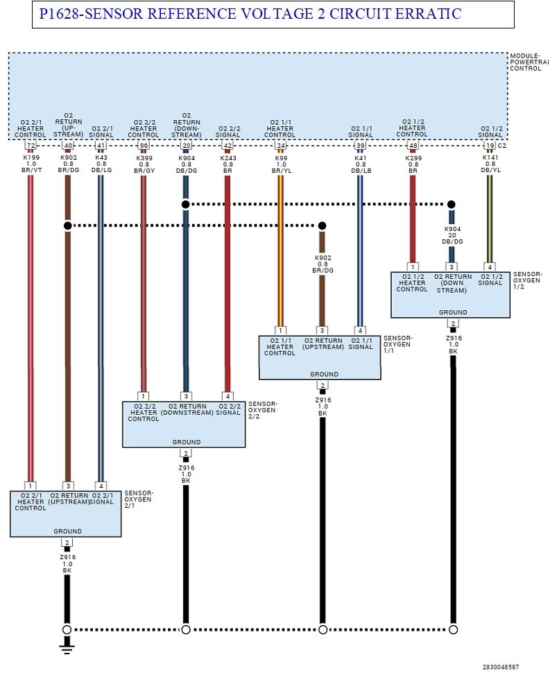
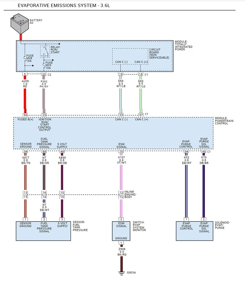
CARADIODOC, Your latest post shows a drawing of oxygen sensors wiring. Yet Your "Theory of operation" and " Diagnostic testing", Have me performing (my original thought) continuity test on the MAP, Cam +++ 5 Volt circuit.
In conclusion, the five volt reference circuit that I was originally asked to Check seems to be working. I do not have a scope available. Although this new scanner Innova 5610 is supposed to have that capability. But I do not know it well enough yet. Has the PCM turned me off? Your suggestions would be greatly appreciated.
Was this
answer
helpful?
Yes
No
+1
Monday, January 22nd, 2024 AT 7:20 PM
Tiny
CARADIODOC
  • MECHANIC
  • 33,883 POSTS
I only picked code P1628 to start with because it is related to all the other codes. It takes me about two hours to copy the steps, and then fix the formatting that doesn't get included. I'm just trying to post the information, even though it doesn't look pretty. I can do the same with any of the other codes, just tell me which one to start with.

I wanted to add a comment of value about the difference between signal ground and actual ground. All of the sensors have ground wires that do go back to ground, but they go through the Engine Computer to do that. This way the computer can monitor that circuit.
As a result of that monitoring circuitry, you're going to find very close to 0.2 volts on those sensor ground wires.

I didn't look at your diagram, but on all the older Chrysler products, there were four ground wires on the Engine Computers. I don't mean the ground wires coming in to it. I mean four that actually bolt to the body sheet metal. One of them is called the "signal" ground. A second one is called the "power" ground. The power ground is for high-current circuits like for the ignition coil(s), injectors, solenoids, and relay coils. None of those are affected by voltage variations, regardless of cause. The problem is there is always a tiny amount of resistance in the wires and the circuitry in the computer. Since you're an electrician, you'll understand what I mean when that resistance causes a voltage drop when current flows through it. Ignition coils and injectors switch on and off, so the current through the ground wire is always changing, and so is the voltage drop. That voltage drop might be in the order of tenths or hundredths of a volt, but that has no affect on those circuits.

If the sensors were grounded on the same ground circuit, they would see those tiny voltage fluctuations. To them, a few hundredths of a volt on the ground wire can translate into a similar variation on their signal wires, and a few hundredths of a volt can have a huge meaning to the computer, especially from the MAP sensor.

I never tried measuring continuity between the various ground wires, so I don't know what "normal" is, but there are separate circuits so the pulsing voltage and current don't affect each other. There was always a second power ground and a second signal ground for redundancy, in case one got cut or corroded.
Was this
answer
helpful?
Yes
No
+1
Monday, January 22nd, 2024 AT 7:55 PM
Tiny
TIMOTHY HUFF
  • MEMBER
  • 36 POSTS
Thank you CARADIODOC, Sounds a lot like the 4 - 20 milliamp signal I use. Also maybe your conversion process isn't needed. What Format are they in? Or if you gentlemen have a suggestion on a service repair manual or website that would be cool.
I was really hoping that you two could put your genius hats on and point me into another direction. I guess I gotta have to do a deeper dive. I keep mentioning my Innova 5610, It is bidirectional supposedly can check modules. Maybe when you guys know more about it than I do and could find it helpful in troubleshooting this.
CARADIODOC I also measured 4.975 volts DC between the control circuit pin and the signal ground pin of the MAP sensor connector. It's unfortunate this truck is my livelihood.
Was this
answer
helpful?
Yes
No
+1
Tuesday, January 23rd, 2024 AT 1:08 PM
Tiny
TIMOTHY HUFF
  • MEMBER
  • 36 POSTS
Other than the PCM what else might all those codes have in common? Can I check the PCM with that Innova 5610?
Was this
answer
helpful?
Yes
No
+1
Tuesday, January 23rd, 2024 AT 1:29 PM

Please login or register to post a reply.

Sponsored links