Hello,
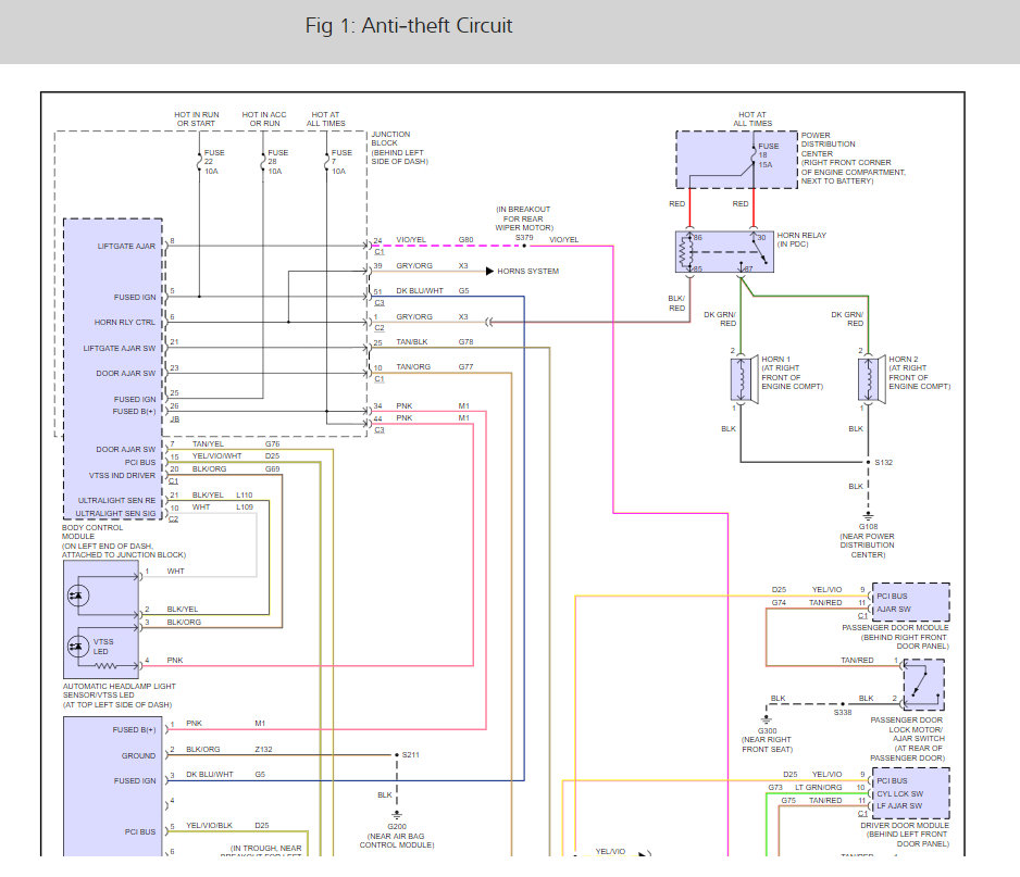
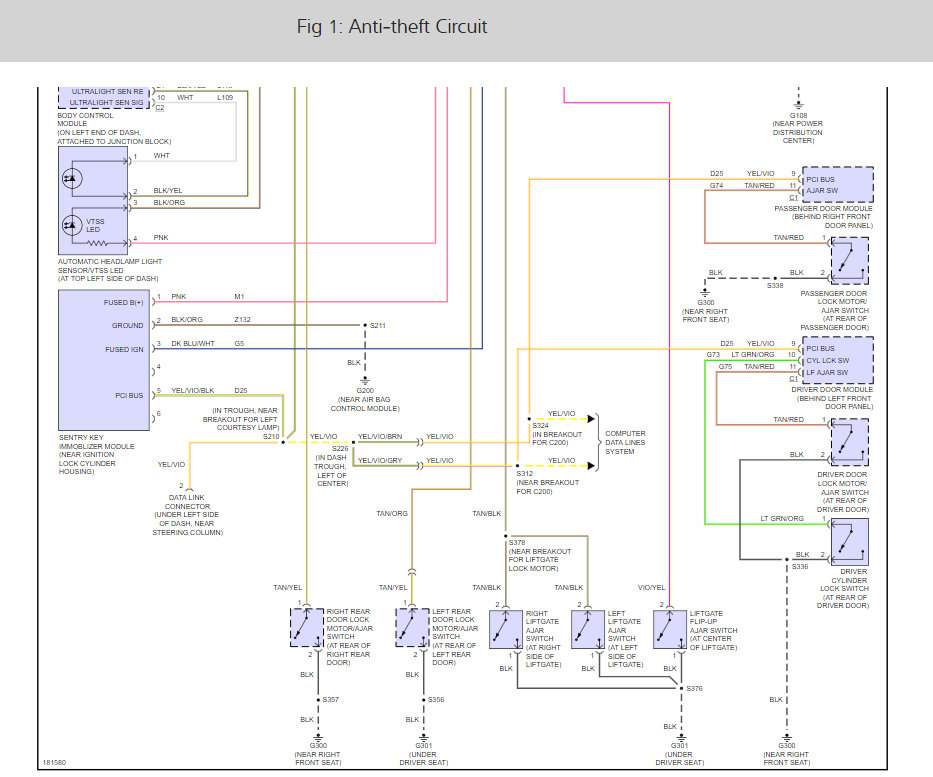
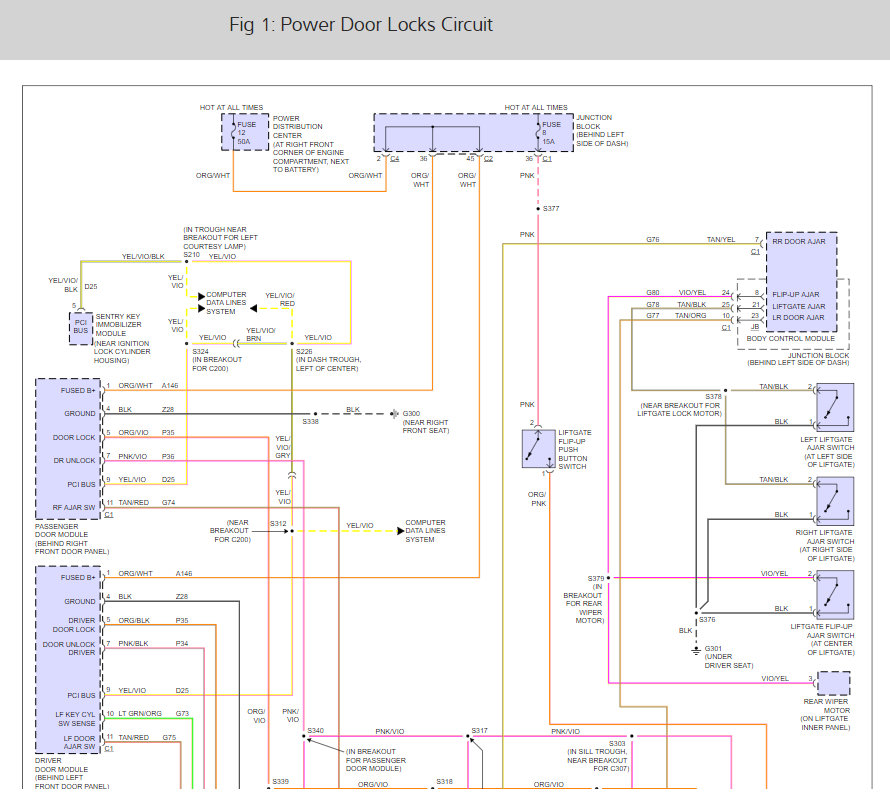
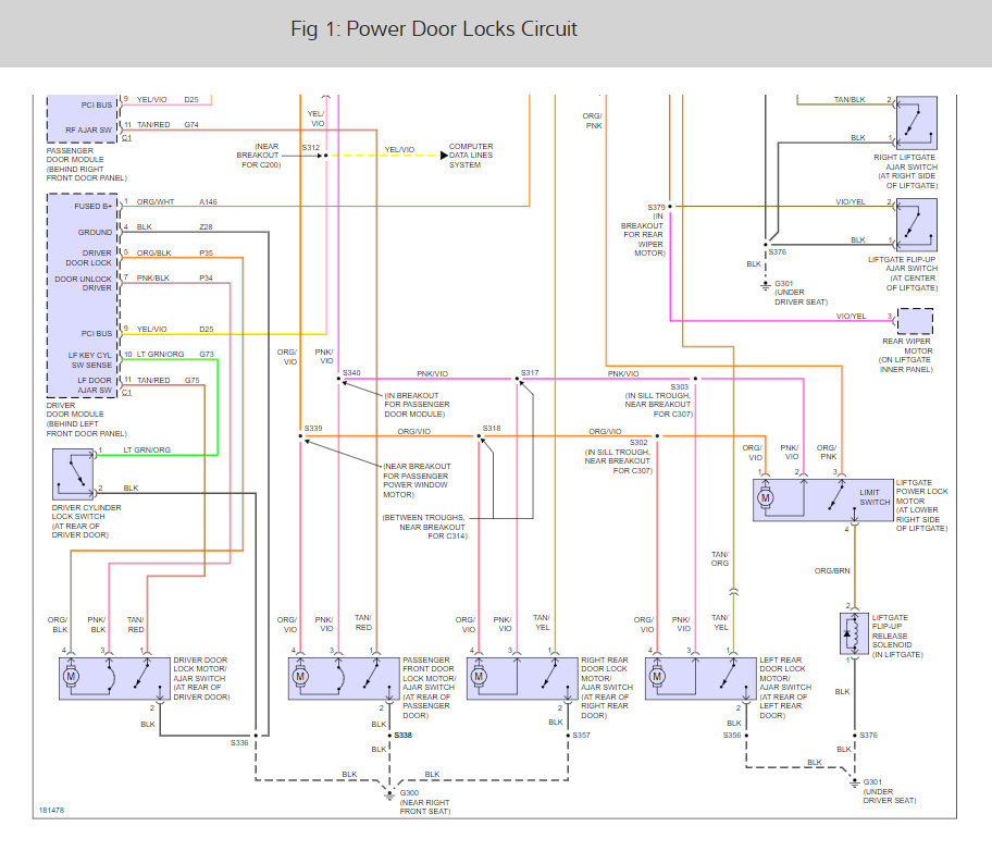
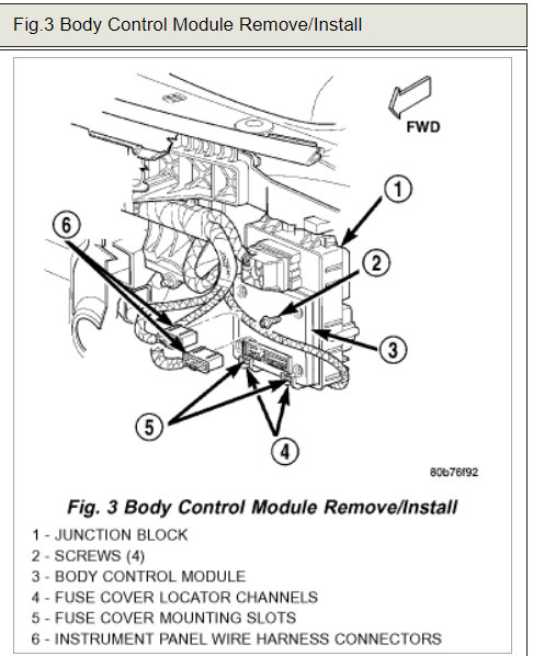
It sounds like the passengers door module is out but to be sure here is the testing process and the door lock and windows so you can see how it works. (Below)
TESTING
If the problem being diagnosed is a rear door window that does not operate from the rear door switch, but does operate from the master switch on the driver side front door, (Refer to DIAGNOSIS AND TESTING - POWER WINDOW SWITCH ). If the problem is a passenger side front or rear window that operates from the switch on that door, but does not operate from the master switch on the driver side front door, use a DRB scan tool and the proper Diagnostic Procedures to diagnose the circuitry of both door modules and the PCI data bus. For complete circuit diagrams, refer to the appropriate wiring information. The wiring information includes wiring diagrams, proper wire and connector repair procedures, details of wire harness routing and retention, connector pin-out information and location views for the various wire harness connectors, splices and grounds.
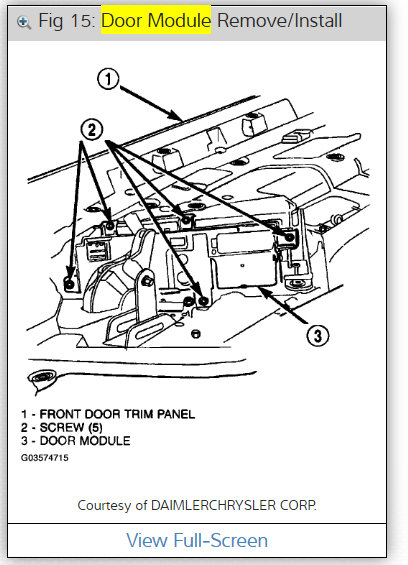
Disconnect and isolate the battery negative cable. Remove the trim panel from the front door, but do not disconnect the door wire harness connectors from the door module. Go to Step 2.
Check the 15-way door wire harness connector for the door module to see that it is fully seated in the door module connector receptacle. If OK, go to Step 3. If not OK, properly connect the 15-way door wire harness connector for the door module to the door module connector receptacle.
Disconnect the 15-way door wire harness connector from the door module connector receptacle. Check for continuity between the ground circuit cavity of the 15-way door wire harness connector for the door module and a good ground. There should be continuity. If OK, go to Step 4. If not OK, repair the open ground circuit to ground as required.
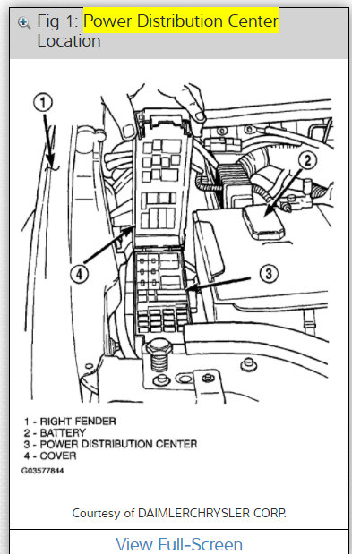
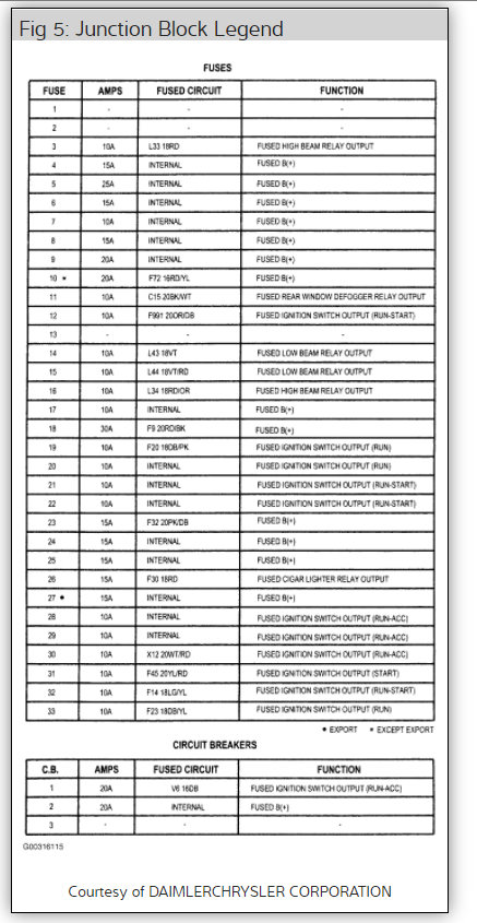
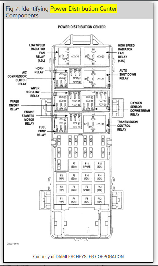
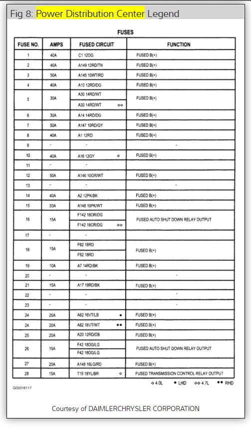
Connect the battery negative cable. Check for battery voltage at the fused B(+) circuit cavity of the 15-way door wire harness connector for the door module. If OK, go to Step 5. If not OK, repair the open fused B(+) circuit to the fuse in the Power Distribution Center (PDC) as required.
If the inoperative window is on a front door, go to Step 6. If the inoperative window is on a rear door go to Step 9.
Disconnect and isolate the battery negative cable. Disconnect the door wire harness connector from the inoperative power window motor wire harness connector. Check for continuity between the front window driver up circuit cavity of the 15-way door wire harness connector for the door module and a good ground. Repeat the check for the front window driver down circuit. In each case there should be no continuity. If OK, go to Step 7. If not OK, repair the shorted front window driver up or down circuit as required.
Check for continuity between the front window driver up circuit cavities of the 15-way door wire harness connector for the door module and the door wire harness connector for the power window motor. Repeat the check for the front window driver down circuit. In each case there should be continuity. If OK, go to Step 8. If not OK, repair the open front window driver up or down circuit as required.
Reconnect the 15-way door wire harness connector back into the door module connector receptacle. Connect the battery negative cable. Connect the probes of a reversible DC digital voltmeter to the door wire harness connector for the power window motor. Observe the voltmeter while actuating the switch for that window in the up and down directions. There should be battery voltage for as long as the switch is held in both the up and down positions, and no voltage in the neutral position. If OK, (Refer to DIAGNOSIS AND TESTING - WINDOW MOTOR ). If not OK, replace the faulty door module.
Check the rear door power window switch continuity. (Refer to DIAGNOSIS AND TESTING - POWER WINDOW SWITCH ). If OK, go to Step 10. If not OK, replace the faulty rear door power window switch.
Disconnect and isolate the battery negative cable. Reconnect the door wire harness connector to the rear door power window switch. Disconnect the door wire harness connector from the inoperative power window motor wire harness connector. Check for continuity between the rear window driver up circuit cavity of the 15-way door wire harness connector for the door module and a good ground. Repeat the check for the rear window driver down circuit. In each case there should be no continuity. If OK, go to Step 11. If not OK, repair the shorted rear window driver up or down circuit as required.
Check for continuity between the rear window driver up circuit cavities of the 15-way door wire harness connector for the door module and the power window motor wire harness connector. Repeat the check for the rear window driver down circuit. In each case there should be continuity. If OK, go to Step 12. If not OK, repair the open rear window driver up or down circuit as required.
NOTE: The door module feeds battery current to both terminals of the rear door power window motors when the power window lockout switch is in the Unlock position, until the master window switch on the driver side front door is actuated. The door module feeds ground to both terminals of the rear door power window motor when the power window lockout switch is in the Lock position, until the master window switch on the driver side front door is actuated.
Reconnect the 15-way door wire harness connector for the door module to the door module connector receptacle. Connect the battery negative cable. Check for battery voltage at each cavity in the door wire harness connector for the power window motor. Each cavity should have battery voltage when the power window switch is in the neutral position. Each cavity should also have battery voltage in one other switch position, either up or down, and zero volts with the switch in the opposite position. If OK, (Refer to DIAGNOSIS AND TESTING - WINDOW MOTOR ). If not OK, replace the faulty door module.
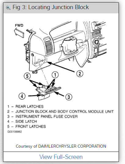
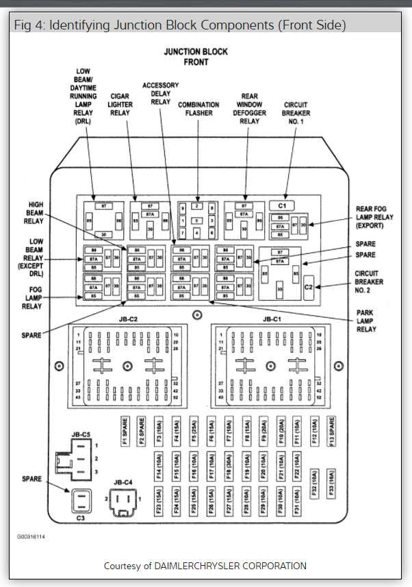
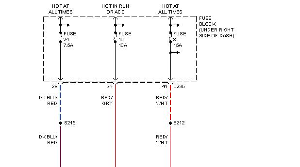
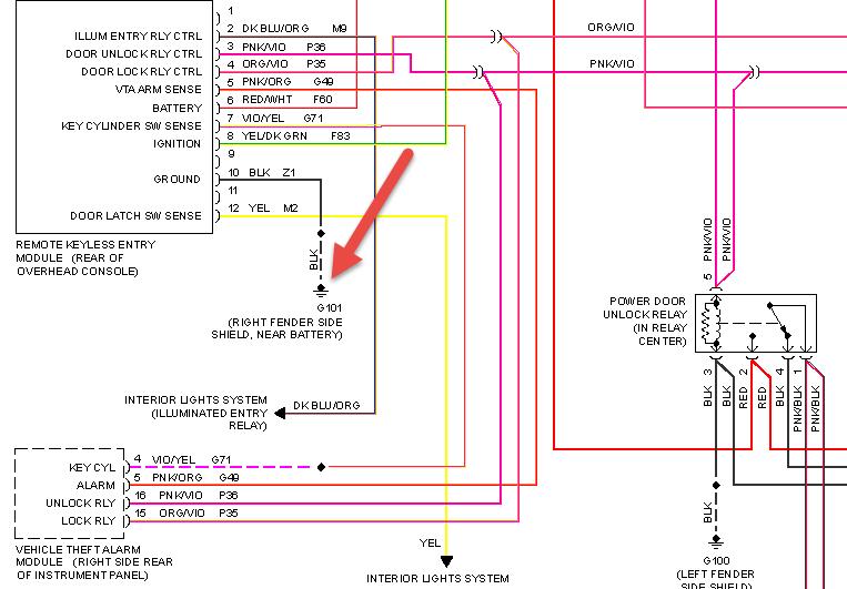
Check out the diagrams (Below). Please let us know what happens.
Cheers, Ken
Images (Click to make bigger)
Saturday, August 29th, 2020 AT 12:38 PM
(Merged)
