Sorry for the delay in replying.
Yes, seems the ECM or its wiring is at fault. I do have the completed diagnostic procedures her, go through them again and see if you get any different results.
DTC P1300 - IGNITER CIRCUIT MALFUNCTION
CAUTION: If ECM replacement is instructed in following testing, always ensure ECM connectors and ground circuit are okay. If either are suspect, repair and repeat testing to confirm ECM malfunction.
Circuit Description The ECM uses pick-up coil input signals to switch primary ignition circuit on and off. Primary circuit is turned off when ECM delivers a signal to igniter on the IGT wire, causing ignition coil to fire spark plug. After delivering a command to turn off primary circuit on IGT wire, the ECM monitors IGF circuit to ensure primary switching occurred. DTC is set when there is no IGF signal to ECM for 4 consecutive IGT signals during engine operation. Possible causes are:
IGF or IGT open or short circuit from igniter to ECM.
Igniter
ECM
Diagnosis & Repair
1. Check for spark at misfiring cylinder. If spark is present, go to next step. If spark is not present, go to step 4 .
2. Check for open or short in IGF circuit between ECM and igniter. Igniter is located near left shock tower. See appropriate wiring diagram in WIRING DIAGRAMS. Repair as necessary. If circuit is okay, go to next step.
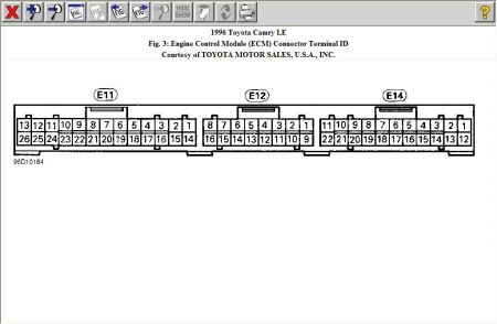
3. Disconnect Black 5-pin igniter connector. Access ECM behind glove box. Turn ignition on. Measure voltage between ground and terminal No. 3 (White/Red wire) at ECM "E11" connector. See Fig. 3 . If voltage is 4.5-5.5 volts, replace igniter. If voltage is not 4.5-5.5 volts, replace ECM and retest.

4. Check for open or short in IGT circuit (White wire) between ECM and igniter. Repair as necessary. If circuit is okay, go to next step.
5. Access ECM behind glove box. Locate ECM "E11" connector. See Fig. 3 . Backprobing ECM connector, measure voltage between ground and terminal No. 20 (White wire) at ECM "E11" connector while cranking engine. If voltage is .1-4.5 volts, go to next step. If voltage is not .1-4.5 volts, replace ECM and retest.
6. Disconnect Black 5-pin igniter connector. Backprobing ECM connector, measure voltage between ground and terminal No. 20 (White wire) at ECM "E11" connector while cranking engine. If voltage is .1-4.5 volts, go to next step. If voltage is not .1-4.5 volts, replace ECM and retest.
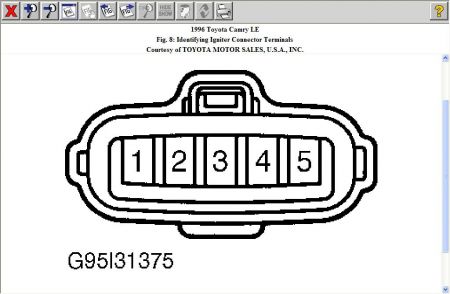
7. Turn ignition on. Measure voltage between ground and terminal No. 3 (White/Red wire) at igniter wiring harness connector. See Fig. 8 . If voltage is 9-14 volts, go to next step. If voltage is not 9- 14 volts, check and repair igniter power source circuit. See appropriate wiring diagram in WIRING DIAGRAMS article.

8. Check for an open or short in wiring harness between ignition switch and ignition coil, and between ignition coil and igniter. Repair as necessary. If wiring is okay, go to next step.
9. Check ignition coil. See IGNITION CHECKS (DISTRIBUTOR TYPE IGNITION SYSTEM) in BASIC TESTING - 2.2L article. Replace coil as necessary. If coil is okay, replace igniter.
SPONSORED LINKS
Was this helpful?
Yes
No
+3
Wednesday, September 20th, 2017 AT 3:09 PM
(Merged)


