Loses speedometer/odometer and very erratic shifting together intermittently

1995 SATURN SC2
130,000 MILES • 1.9L • 4 CYL • 2WD • AUTOMATIC
Avatar
MARC GAGNON
  • MEMBER
  • 42 POSTS
Problem surfaced with every once in a while the car would not show power at ignition when trying to start. Everything else powered worked except when I attempted to engage starter. If you waited and tried again it would start. Now something different has developed as well. Upon startup speedometer isn’t working and car is shifting very erratically hard shifts premature shifts up or down and at times hard in neutral or reverse. Then suddenly car will come out of most all symptoms and speedometer will return. If power down the car and try again symptoms return immediately and may or may not disappear again. I first changed the I/O speed sensor (Only one on this car correct?) because all symptoms are pointing to this. Has not changed. I'm fearing solenoids at this point. Or PCM? Car also has new starter and battery. Charging system shows perfect.
Mar 11, 2020 at 2:52 PM
Advertisement
Avatar
JACOBANDNICKOLAS
  • CERTIFIED EXPERT
  • 110,175 POSTS
Hi,

I realize you replaced the sensor, but what you described sounds related. Is the wiring and the connection in good condition?

https://www.2carpros.com/articles/how-to-check-wiring

Next, I attached a pic below. Is the sensor in the pic the one that was replaced? Also, I need you to check the ground shown in the pic. Make sure it is tight, clean (not corroded) or damaged.

Let me know what you find.

Joe
Mar 12, 2020 at 5:24 PM
Avatar
MARC GAGNON
  • MEMBER
  • 42 POSTS
Hi, and thanks for the response and the great information. What you said definitely rings a bell with what I did today and how it is relating to the issues. Today I focused on cleaning up the grounds throughout and found many with some corrosion. The worst thing I found was that my side posts on my battery weren’t making solid contact especially the ground. So I reconfigured posts to a stronger connection. I also tested the solenoids in the valve body and they all showed within range. I rechecked the connections in the diagram that you sent me on the neutral safety switch and checked and readjusted the switch. The connector had some corrosion and had a slight looseness to it. I cleaned up and tightened connection. The last thing I did was recheck the speed sensor two prong connector as well as recheck the ohm measurement at 800 ohms. I failed to mention that the old sensor was seeping oil into the connector. I noticed this when I replaced. I'm wondering if some oil got up into the two wires and that along with some bad grounding throughout along with the neutral safety switch Ground wire being of poor connection was creating multiple issues. Well after doing all this the car was a whole different car. Ran smooth. Speedometer was back and shifted extremely smooth. No symptoms until after half hour of all different speeds car showed small low speed shifting variances but nothing like before and didn’t lose speedometer. I turned car off then took for another test after 15 min . No issues with this ride. Was wondering if PCM was relearning? I haven't seen the car run and have so much pep and shift this well ever. Really. I haven’t gotten as far as chasing wires back to PCM but that's next if issues continue. Really need to get a good shop manual for this car...
Mar 12, 2020 at 7:07 PM
Advertisement
Avatar
MARC GAGNON
  • MEMBER
  • 42 POSTS
Oh and yes the sensor in the diagram is the same. Also, here is a shot of my battery connection now:
Mar 12, 2020 at 7:10 PM
Avatar
JACOBANDNICKOLAS
  • CERTIFIED EXPERT
  • 110,175 POSTS
Glad you got it fixed. Let us know if you need help in the future. And, a bad ground plays havoc with everything. LOL It's frustrating at times.
Mar 12, 2020 at 7:16 PM
Avatar
MARC GAGNON
  • MEMBER
  • 42 POSTS
Thank you very much. I'm going to run it through the paces tomorrow and see how things go. To think I was ready to buy an instrument cluster, lol.
Mar 12, 2020 at 7:23 PM
Avatar
JACOBANDNICKOLAS
  • CERTIFIED EXPERT
  • 110,175 POSTS
You are very welcome.
Mar 12, 2020 at 7:31 PM
Avatar
MARC GAGNON
  • MEMBER
  • 42 POSTS
I thought I had it. After sitting for the night, I started the car and let it warm went for a ride. Five miles into it speedometer and rpm went jerky on me as well as transmission erratically shifting and what not. I pulled over and used paperclip to retrieve code. Code 42 shows. (Open/bypass circuit). Where would you start? At VSS connector? Cluster? PCM?
Mar 14, 2020 at 5:57 AM
Avatar
MARC GAGNON
  • MEMBER
  • 42 POSTS
Also, how the codes read from SES light and coolant temperature light are as follows: from SES code 12 three times, code 11 three times, then code 42 three times from coolant light.
Mar 14, 2020 at 6:45 AM
Avatar
JACOBANDNICKOLAS
  • CERTIFIED EXPERT
  • 110,175 POSTS
I would start with the SES issue. Pics 1-3 are for trouble shooting. Here is the info related to the code 11. It is a transmission related code. Basically, when you find a code 11, it indicates there are other codes present. I suspect it is related to the SES codes.

DTC 11 - TRANSAXLE DIAGNOSTIC TROUBLE CODES PRESENT
The powertrain control module, used on vehicles equipped with automatic transaxles, contains an engine control module (EC) and a transaxle control module (TC). These control modules communicate internally over a serial peripheral interface (SPI) bus. When the transaxle control module (TC) detects a malfunction in the automatic transaxle, a DTC is stored in the transaxle control module's memory and an indication is sent to the engine control module to turn on the malfunction indicator lamp. If the DLC is grounded, the transaxle diagnostic trouble codes flash on the HOT light telltale located in the instrument cluster. (Refer to Auto Transaxle diagnostic trouble codes.) See: Computers and Control Systems > Testing and Inspection

DTC PARAMETERS
^ DTC 11 will set if the PCM/TC has set a transaxle diagnostic trouble code.

DIAGNOSTIC AIDS
^ Search the scan tool for stored transaxle codes. Select TCM trouble codes.

When the PCM/TC codes are cleared, DTC 11 will also be cleared from general information but not from Malfunction history.

^ Code 11 will not set if transaxle flags are present.

_________________________
The code 42 is related to the ABS can bus system (wiring). Here is the info and the last two pics correlate with this. Pic 4 is a diagnostic flow chart.

1995 Saturn Sedan L4-1.9L DOHC VIN 7
Antilock Braking System (ABS)
Vehicle ALL Diagnostic Trouble Codes ( DTC ) Testing and Inspection Manufacturer Code Charts DTC 42 Antilock Braking System (ABS)
ANTILOCK BRAKING SYSTEM (ABS)
Diagnostic Chart
imageOpen In New TabZoom/Print

ABS Modulator Motor Pack
imageOpen In New TabZoom/Print


REAR ESB DOES NOT HOLD MOTOR
The expansion spring brakes (ESB) are used on both front and rear actuator motor assemblies. The spring expands to provide friction to prevent the modulator piston from being back-driven by hydraulic pressure. This condition will disable rear base brakes and turn On the antilock and brake telltale.

CODE PARAMETERS

Code 42 sets if:
^ Rear ESB does not hold motor.
^ This code can only set during initialization.
^ This code can be set after an ABS stop if this channel did not get into ABS.

DIAGNOSTIC AIDS
The ESB (enterprise service bus) is an internal component of the ABS motor pack and can not be serviced separately. If it is determined to be faulty, the motor pack must be replaced.

WARNING: When replacing motor pack do not place hands near the motor/modulator gears. The gears may have enough preloaded tension to cause personal injury.

Use Scan tool to perform ABS motor tension release special test before removing motor pack.

When the ignition is cycled On, the ABS module verifies motors are in home position.

The ABS system will initialize (run motors down then up) when the vehicle is driven at least 13 km/h (8 mph) after start-up.

NOTE: Initialization alternates between left front/rear and right front/rear each ignition cycle.

When attempting to diagnose an intermittent problem, use the Scan tool[1] to review supplemental diagnostic information. The supplemental data can be used to duplicate a problem.

[1] Select Malfunction History from Scan tool ABS menu.

____________________

Also, code 42 is set when there is an issue with the vss. I suspect we have a wiring issue and not a component. Double check the connections at the vss. Make sure none of the pins are damaged, corroded, or pushed out of position.

Let me know what you find.

Take care,
Joe
Mar 14, 2020 at 6:20 PM
Avatar
MARC GAGNON
  • MEMBER
  • 42 POSTS
Hi Joe now the code 42 makes sense. The ABS is inoperable in the car. A while ago it was found that the front was beyond repair at the wheel so decided to not use. I have been using without fuse in the uhfb. I forgot and installed after this repair of VSS and the ABS activated while testing. Now that would explain the code 42 present. So I took fuse back out and ran and so far no more code 42 just getting the 41 now. Tomorrow I will replace the VSS connector. I did test voltage at the plug and it was 12.6 volts. The plug seems fine but the connectors themselves seem kind of large or stretched also maybe oil has seeped into the wires from the old sensor weeping and causing an issue. But voltage shows good. I will report back tomorrow. Thanks for your help
Mar 14, 2020 at 8:22 PM
Avatar
JACOBANDNICKOLAS
  • CERTIFIED EXPERT
  • 110,175 POSTS
Sounds like a plan. I attached three pics below relevant to these testing directions. I figured I would add them just in case.

__________________________________


NO VEHICLE SPEED SENSOR SIGNAL
DTC 41 indicates no vehicle speed signal pulses are present on circuit 400/400A at the PCM. Vehicle speed values are provided by the vehicle speed sensor. The sensor is a permanent magnet (PM) generator mounted on the differential area of the transaxle converter housing. The PM generator produces a pulsing voltage whenever vehicle speed is above 5 km/h (3 mph). These pulses occur 16 times per each revolution of the differential housing and are translated to provide vehicle speed in miles per hour. The km/h (mph) value read on the Scan tool TCM menu may very slightly from the ECM data or the speedometer.

DTC PARAMETERS
DTC 41 is set when the PCM has detected the following conditions after starting from a stop.
^ No vehicle speed. Vehicle speed = zero.
^ Turbine speed above 1400 rpm.
^ Steady moderate throttle.
^ Speed ratio across the torque converter is greater than 700 rpm.
^ During a 1-2 upshift the turbine speed pulls down by a one to two ratio. This diagnostic commands TCC off during a 1 to 2 shift.

TEST DESCRIPTION
Numbered steps below refer to steps on trouble chart.
1. This step verifies the problem is still present.
2. This test indicates if problem is PCM or a wiring/sensor problem.
3. An open or shorted sensor will set DTC 41. This test indicates if problem is a wiring problem or a faulty sensor.
4. An open, ground or a short to voltage in circuits 400/400A or 401/401A will cause DTC 41 to set. This step indicates which circuit is faulty.

DIAGNOSTIC AIDS
When attempting to diagnose an intermittent problem use the Scan tool[1] to review supplemental diagnostic information. The supplemental data can be used to duplicate a problem.

Check the tightness of the female terminal grip with a spare male terminal.

^ Check wire routing for possible chafed wires.


[1] Select Malfunction History from Scan tool TCM menu.
________________________________________________________________________

Let me know what you find.

Take care,
Joe
Mar 14, 2020 at 8:30 PM
Avatar
MARC GAGNON
  • MEMBER
  • 42 POSTS
Hi there. Well the great news is that it looks like I have finally fixed the issue. It ended up being the connector. Switched it out this morning and did a fifty mile test run with allowing multiple shutoffs and restarting. So thanks for the great info and schematics and taking the time to help out I appreciate it. The were some other SES codes that came up during running today. Which I assume are coming back up due to PCM resetting? Well code 26 and 32 are both coming up consistently. The car seems to act fine but id like to resolve. Once again do you have some starting points for me? Thanks so much.
Mar 15, 2020 at 11:38 AM
Avatar
JACOBANDNICKOLAS
  • CERTIFIED EXPERT
  • 110,175 POSTS
Hi,

First, you are very welcome. The two codes that you mentioned can both be related to the transmission. However, the 26 gives me a range of components that it can be related to. See picture 1.

Code 32 is most likely related to the transmission temperature sensor. See pic 2 for location. If you have cleared the codes and they returned, check the connector on the temp sensor. If it is good, replace the sensor. If you want to check it first, here are the test procedures. They coordinate with pics 3 and 4.


____________________________


TRANSAXLE TEMPERATURE CIRCUIT GROUNDED (HOT)
The transaxle temperature circuit monitors transaxle fluid temperature by using a thermistor (sensor) located in a transaxle pressure port near the pressure filter. Sensor resistance will increase as temperature decreases and decreases as the temperature increases. The PCM/TC supplies a five volt signal to circuit 585 and monitors the voltage on the internal signal line as it varies up and down with circuit resistance. The voltage value on the signal line is converted to a temperature value.

DTC PARAMETERS
DTC 32 is set when the PCM/TC has detected the following conditions for longer than 30 seconds.
^ Engine coolant temperature below 100°C (212°F).
^ Sensor reading is above 140°C (284°F).

TEST DESCRIPTION
Numbered steps below refer to numbered steps on chart.

NOTE: High temperature equals low sensor resistance.

1. This step verifies the problem is still present. If Scan tool indicates temperature is less than 140°C (248°F) the conditions for DTC 32 are not currently present.
2. This step simulates a DTC 31 - Transaxle Temperature circuit Open (Cold). If the PCM recognizes the high signal (low temperature) and the Scan tool reads less than -37°C (-35°F) the PCM and wiring are OK. With IGN on five volts at sensor harness terminal for circuit 585 indicates PCM and circuit 585 are OK.

DIAGNOSTIC AIDS
When attempting to diagnose an intermittent problem use the Scan tool[1] to review supplemental diagnostic information. The supplemental data can be used to duplicate a problem.

Check the tightness of the female terminal grip with a spare male terminal.

^ DTC 32 is not set on overheated transaxle. That would cause information flag 15 Hot Lamp illuminated to set.

[1] Select Malfunction History from Scan tool TCM menu.

___________________________

As far as the 26, if I look under transmission, here is what is listed.

1995 Saturn Sedan L4-1.9L DOHC VIN 7
Transmission Controls With PCM
Vehicle ALL Diagnostic Trouble Codes ( DTC ) Testing and Inspection Manufacturer Code Charts DTC 26 Transmission Controls With PCM
TRANSMISSION CONTROLS WITH PCM
Diagnostic Chart

pic 5

Circuit Schematic

pic 6


TCC STUCK ON
When TCC is commanded off, the engine speed to turbine speed ratio (delta) is monitored to assure TCC is off. TCC stuck on indicates that TCC was commanded off but the actual ratio (delta) across the torque converter, (engine speed/turbine speed), is one to one or TCC on. TCC is turned off by opening circuit 422 at the PCM/TC. A TCC stuck on will usually cause the engine to stall when reverse is selected.

DTC PARAMETERS
DTC 26 is set when the PCM has detected the following conditions for more than four seconds twice per ignition cycle.
^ Engine speed greater than 908 rpm.
^ Turbine speed is between 224 and 2800 rpm.
^ TCC is commanded to release for more than 0.25 seconds.
^ Load value (engine torque) is greater than 100.
^ Speed delta (engine speed - turbine speed) across torque converter is less than 84 rpm.

TEST DESCRIPTION
Numbered steps below refer to numbered steps on chart.
1. Check for information flags 79 or 96. They must be eliminated first as a possible cause of DTC 26.

NOTE: Prior to performing actuator quick check, the fuel pump probe hole must be connected to 12 volts. See "Actuator Quick Check" procedures. See: Automatic Transmission/Transaxle > Component Tests and General Diagnostics


2. Check actuator operation. The actuator quick test will PWM the actuators at a set rate. Listen and compare the noise of TCC gear actuator to that of other actuators. The noise of all should be similar.
3. The TCC release circuit may be leaking at the seal ring on the input shaft. This would allow release pressure to leak off to converter out circuit or lube circuit. Also a remote possibility is the ball pressed into the input shaft is loose.

DIAGNOSTIC AIDS

^ When the PCM detects a fault in the circuit (open, ground, short), the PCM will open the circuit internally to protect the circuit.
^ The TCC may be detected as- stuck on when the transaxle is put into drive range. If TCC is stuck on at start-up, a stall may occur, and after a restart it will result in a 3rd or 4th gear start.

___________________________


Let me know if this helps.

Joe
Mar 15, 2020 at 5:37 PM
Avatar
MARC GAGNON
  • MEMBER
  • 42 POSTS
Thanks Joe, but these didn’t come in as trans-axle codes. They were SES codes that followed a code 12 not 11. Wouldn't this point in a different direction? Thanks.
Mar 15, 2020 at 6:23 PM
Avatar
JACOBANDNICKOLAS
  • CERTIFIED EXPERT
  • 110,175 POSTS
Don't laugh, but by SES are you referring to Service Engine Soon?

Because of the model year, the OBD systems were in transition from OBD1 to OBD2. I show codes for both systems, but with the OBD1 codes, they need broken into component areas. Ugh. Anything to make things more confusing. LOL

Let me know.
Joe
Mar 15, 2020 at 6:35 PM
Avatar
MARC GAGNON
  • MEMBER
  • 42 POSTS
Yes, I am referring to the SES light codes. I don't have a scanner. But yeah I have been a little confused about how it was all broken down. But this set of codes all showed up on the SES light blinking after the code 12. No code 11 this time. The oil temperature light wasn't involved this time either.
Mar 15, 2020 at 6:43 PM
Avatar
MARC GAGNON
  • MEMBER
  • 42 POSTS
And from what I understand this is an obd 1 system.
Mar 15, 2020 at 6:44 PM
Avatar
JACOBANDNICKOLAS
  • CERTIFIED EXPERT
  • 110,175 POSTS
Hi,

Yes, it is an OBD1. 1995 was the transition year. Most have obd2 but some still had the obd1.

Now the tough part is the code. The way GM broke them down was one code could be related to different systems. That is where I am stumped. I'm not sure which way to direct you. If you can pinpoint which area you would like to focus on based on symptoms, I would be more helpful. Sorry, I just don't want to confuse you.

Joe
Mar 15, 2020 at 7:23 PM
Avatar
MARC GAGNON
  • MEMBER
  • 42 POSTS
Okay. Well there was a difference in the way the codes 26 and 32 came up on the dash. When I was addressing the codes for the VSS, those codes came up on the dash by first blinking the SES code 12 three times to know it was in the diagnosis mode then it flashed a code 11 letting me know it was a trans-axle code then it flashed the code 41 on the oil temps light. Its not presenting itself this way with code 26 and 32 its all on the SES light so I assumed it was different from the trans-axle codes.
Mar 15, 2020 at 8:19 PM
Avatar
MARC GAGNON
  • MEMBER
  • 42 POSTS
See here are the charts that I have been kinda working with here one being trans-axle codes. I thought is was the way that it flashed on the dash is what made the difference as I was explaining. Don’t know if I’m making sense here, lol.
Mar 15, 2020 at 8:23 PM
Avatar
JACOBANDNICKOLAS
  • CERTIFIED EXPERT
  • 110,175 POSTS
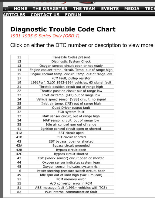
For the code 26, I am showing a fault with the quad driver module. This is an internal PCM component. The 32 is related to the EGR circuit. I have done a bit of research and found the most common cause of these two codes to appear together is the EGR solenoid. After continuing, I came across a technical service bulletin. Take a look at this. It indicated what needs checked.

_________________________

1995 Saturn Sedan L4-1.9L DOHC VIN 7
Engine Controls - DTC's 26, 32 & Flag 27 Manual Updates
Vehicle Powertrain Management Technical Service Bulletins Engine Controls - DTC's 26, 32 & Flag 27 Manual Updates
ENGINE CONTROLS - DTC'S 26, 32 & FLAG 27 MANUAL UPDATES
BULLETIN NO.: 96-T-08

ISSUE DATE: January, 1996

GROUP/SEQ. NO.: Engine-01

CORPORATION NO.: 686001

SUBJECT:
Diagnostic Service Information on PCM/EC DTCs 26 and 32, and Information Flag 27

MODELS AFFECTED:
1991 - 1995 Saturns

PURPOSE:
The diagnostic flow carts for diagnostic trouble code (DTC) 26 and Information Flag 27, in the "1991-1994 Electronic Engine Controls Service Manual," and for DTCs 26 and 32 and for Information Flag 27 in the "1995 Electronic Engine Controls Service Manual" have incorrect resistance specifications. Also, some of the resistance specifications under the "Diagnostic Aids" for these DTCs and Information Flags are incorrect.

It is important to note that only a short or open in a solenoid, relay, bulb or related wiring or electrical connections can cause the PCM to set DTCs 26 or 32, or Information Flag 27. A resistance in the output circuits between 5 and 10,000 ohms will not cause DTCs 26 or 32, or Information Flag 27.

Beginning diagnosis with resistive measurements of the solenoid will likely result in mis-diagnosis. If the fault is present during diagnosis, follow the diagnostic flow chart for the DTC or Information Flag. If the fault is intermittent, attempt to test the quad driver module (QDM) outputs under similar operating conditions as represented by the malfunction (MALF) history records, stored in the PCM. Exercise the QDM with "Special Test" function in the portable diagnostic tool (PDT) or service stall system (SSS).

If a solenoid or relay is not within the specifications stated under the "Diagnostic Aids" for the DTC or Information Flag, it does not mean that the solenoid or relay was the reason the DTC or Information Flag was set. It could mean that the solenoid or relay operates sluggishly or too rapidly, but unless the solenoid or relay opened or shorted, it cannot have caused the DTC or Information Flag to have been set in PCM memory.

Refer to the chart following and make the corrections in the service manuals as noted. 1991-1994 Electronic Engine Controls Service Manual

^ Page ENEC 70 (DTC 26), under "Diagnostic Aids," change:

- EGR solenoid resistance specification from 37-44 ohms to 20-50 ohms.

- EVAP canister purge solenoid resistance specification from 22-42 ohms to 20-50 ohms.

^ Page ENEC 72 (DTC 26), in first box of flow chart, change:

- EGR solenoid resistance specification from 37-44 ohms to 5-10,000 ohms.

- EVAP canister purge solenoid resistance specification from 22-42 ohms to 20-50 ohms.

^ Page ENEC 120 (Information Flag 27), under "Diagnostic Aids," change:

- EGR solenoid resistance specification from 37-44 ohms to 20-50 ohms.

- EVAP canister purge solenoid resistance specification from 22-42 ohms to 20-50 ohms.

1995 Electronic Engine Controls Service Manual

^ Page ENEC 68 (DTC 26), under "Diagnostic Aids," change:

- Linear EGR solenoid resistance specification from 7-9 ohms to 7-10 ohms.

- EVAP canister purge solenoid resistance specification from 22-42 ohms to 20-50 ohms.

^ Page ENEC 69 (DTC 26), in the flow chart box "is the resistance of the EVAP canister purge solenoid between 22-42 ohms?" change resistance specification to 20-50 ohms.

^ Page ENEC 72 (DTC 32), under "Diagnostic Aids," change:

- Linear EGR solenoid resistance specification from 7-9 ohms to 7- 10 ohms.

- EVAP canister purge solenoid resistance specification from 22-42 ohms to 20-SO ohms.

^ Page ENEC 114 (Information Flag 27), under "Diagnostic Aids," change;

- Linear EGR solenoid resistance specification from 7-9 ohms to 7-10 ohms.

- EVAP canister purge solenoid resistance specification from 22-42 ohms to 20-50 ohms.

^ Page ENEC 115 (Information Flag 27), in the flow chart box "Is the resistance of the EVAP canister purge solenoid between 22-42 ohms?" change resistance specification to 20-50 ohms.

Joe
Mar 15, 2020 at 8:40 PM
Avatar
MARC GAGNON
  • MEMBER
  • 42 POSTS
Okay, so for example the EGR solenoid could be operating sluggishly due to the flag that's apparent with SES light? So I should measure the resistance on the solenoid to evaluate? Boy they didn’t make this easy, lol.
Mar 15, 2020 at 8:54 PM
Avatar
MARC GAGNON
  • MEMBER
  • 42 POSTS
Hi,
I am a little confused at this point as to how to actually physically test the resistance on the EGR solenoid. I can’t find the pin layout and the sequence of which pins to actually test for proper resistance. In other words where am I going to place the probes from multi-meter? I do understand the ohms rating change but also confused that the test is not reliable at this point if done first. I thought that either its a bad solenoid or it good based on resistance? Thanks so much.
Mar 16, 2020 at 5:11 AM
Avatar
JACOBANDNICKOLAS
  • CERTIFIED EXPERT
  • 110,175 POSTS
Hey buddy, sorry I forgot the pin layout. And I couldn't agree more with you. Nothing is easy. Wait until you get to deal with can bus circuits. LOL One wire covering multiple circuits!!!

I attached a pic of the pin layout for you. Let me know if it helps.

Joe
Mar 16, 2020 at 8:04 AM
Avatar
MARC GAGNON
  • MEMBER
  • 42 POSTS
Forgive me for asking a stupid question, but can you tell me which pins i am connecting to to check ohm level?
Mar 16, 2020 at 8:09 AM
Avatar
JACOBANDNICKOLAS
  • CERTIFIED EXPERT
  • 110,175 POSTS
No question is stupid. Pins A and B. Note that you are checking the sensor and not the supply, so determine which pins are A and B on the solenoid.
Mar 16, 2020 at 8:19 AM
Avatar
MARC GAGNON
  • MEMBER
  • 42 POSTS
Okay, yes the solenoid. It looks like 1 ohm there.
Mar 16, 2020 at 8:26 AM
Avatar
MARC GAGNON
  • MEMBER
  • 42 POSTS
And im checking a to ground then b to ground? Or a to b?
Mar 16, 2020 at 8:30 AM
Avatar
JACOBANDNICKOLAS
  • CERTIFIED EXPERT
  • 110,175 POSTS
You need to check A to B.
Mar 16, 2020 at 8:37 AM
Avatar
MARC GAGNON
  • MEMBER
  • 42 POSTS
Doesn’t show any resistance.
Mar 16, 2020 at 8:43 AM
Avatar
JACOBANDNICKOLAS
  • CERTIFIED EXPERT
  • 110,175 POSTS
There should be something unless it shorted internally. You may have found the problem. If there is nothing, it has to be bad.
Mar 16, 2020 at 9:08 AM
Avatar
MARC GAGNON
  • MEMBER
  • 42 POSTS
Pin b to c show 1.4 ohms on new EGR. Pin a to b zero resistance.
Mar 16, 2020 at 9:51 AM
Avatar
MARC GAGNON
  • MEMBER
  • 42 POSTS
And same on existing EGR.
Mar 16, 2020 at 10:00 AM
Avatar
MARC GAGNON
  • MEMBER
  • 42 POSTS
So I have gone back to test driving and paying attention to symptoms and when flags present themselves or the SES lights up. Today I correlated transmission symptoms with the SES lighting briefly ( happened 3 different times) then pulling the code via shorting pins a and b. Code 26 comes up. When the SES lights up it correlates with the torque converter acting funny. So it appears that you were on the right track with diagnosis. The code 32 hasn’t come back yet but I haven't taken on highway yet. Code 26 states converter is getting stuck and that's what it feels like. Do you have a procedure for diagnostics with the code 26 (TCC stuck)?
Mar 16, 2020 at 12:19 PM
Avatar
JACOBANDNICKOLAS
  • CERTIFIED EXPERT
  • 110,175 POSTS
Good eye! Here is what I have. The two pics correlate with this info.

________________________________


TCC STUCK ON
When TCC is commanded off, the engine speed to turbine speed ratio (delta) is monitored to assure TCC is off. TCC stuck on indicates that TCC was commanded off but the actual ratio (delta) across the torque converter, (engine speed/turbine speed), is one to one or TCC on. TCC is turned off by opening circuit 422 at the PCM/TC. A TCC stuck on will usually cause the engine to stall when reverse is selected.

DTC PARAMETERS
DTC 26 is set when the PCM has detected the following conditions for more than four seconds twice per ignition cycle.
^ Engine speed greater than 908 rpm.
^ Turbine speed is between 224 and 2800 rpm.
^ TCC is commanded to release for more than 0.25 seconds.
^ Load value (engine torque) is greater than 100.
^ Speed delta (engine speed - turbine speed) across torque converter is less than 84 rpm.

TEST DESCRIPTION
Numbered steps below refer to numbered steps on chart.
1. Check for information flags 79 or 96. They must be eliminated first as a possible cause of DTC 26.

NOTE: Prior to performing actuator quick check, the fuel pump probe hole must be connected to 12 volts. See "Actuator Quick Check" procedures. See: Automatic Transmission/Transaxle > Component Tests and General Diagnostics


2. Check actuator operation. The actuator quick test will PWM the actuators at a set rate. Listen and compare the noise of TCC gear actuator to that of other actuators. The noise of all should be similar.
3. The TCC release circuit may be leaking at the seal ring on the input shaft. This would allow release pressure to leak off to converter out circuit or lube circuit. Also a remote possibility is the ball pressed into the input shaft is loose.

DIAGNOSTIC AIDS

^ When the PCM detects a fault in the circuit (open, ground, short), the PCM will open the circuit internally to protect the circuit.
^ The TCC may be detected as- stuck on when the transaxle is put into drive range. If TCC is stuck on at start-up, a stall may occur, and after a restart it will result in a 3rd or 4th gear start.

________________________________________

Let me know if this helps.

Take care,

Joe
Mar 16, 2020 at 1:22 PM
Avatar
MARC GAGNON
  • MEMBER
  • 42 POSTS
Okay, Joe. looks like this is where I get off. Apparently this is over my skill level. I really don't know which way to go with this next. I have read and reread the last info that you sent me and it's just not making any sense to me. I do thank you for trying to help out though.
Take care,
Marc
Mar 16, 2020 at 3:35 PM
Avatar
JACOBANDNICKOLAS
  • CERTIFIED EXPERT
  • 110,175 POSTS
Marc,

The directions incorporate the use of an OBD1 scanner. That is why it may be confusing you. I have to be honest, I work on them all the time and don't have an OBD1 scanner. If you do, let me know.

Joe
Mar 16, 2020 at 4:22 PM
Avatar
MARC GAGNON
  • MEMBER
  • 42 POSTS
Thanks Joe I don’t have a scanner. The weird thing about all this which makes it all so confusing is that these codes aren’t even coming up as trans-axle codes. They are not lighting up the red hot light to identify them as trans-axle codes. The other code 11’s that I got worked that way. These codes are just lighting up the SES light. So I don’t even know if I'm on the right track here and I am confused as to what step to take next. The other weird thing is that the new EGR that I measured for resistance on pin a and pin b came in as nothing just like mine does. That's why I didn't buy and install. I probably have a combo of things going on at once here and not quite sure where to begin to Identify them. I do know that I have 12.5 volts coming into EGR and 5.6 going out. As far as resistance at pins ab there is none. Transmission shifts harder than it should and the TCC get wonky at 45 steady easy rpm's. Seems to go in and out and sticks upon acceleration whether its locked in or not. When I come to a stop that's when SES comes on sometimes briefly sometimes stays on. Man I wish this thing was a 1996!
Mar 16, 2020 at 4:50 PM
Avatar
JACOBANDNICKOLAS
  • CERTIFIED EXPERT
  • 110,175 POSTS
If it was a 1996, that would make things a lot easier. As far as the 5.6V, that sounds correct. The shifting issues and TCC issues I feel are all tied to the problem.

When you look through the TCC diagnostic steps, what part is confusing to you? Is there something I can do to try and help?

Joe
Mar 16, 2020 at 6:03 PM
Avatar
MARC GAGNON
  • MEMBER
  • 42 POSTS
First I'm not able to see 79 or 96 flags and don’t understand what they are.
The whole note on the fuel pump and see actuator pump quick check I don’t understand what that is or how to perform. And how do I perform step 2 and 3? Is there something missing in the procedure a link maybe or a chart? I'm sure its me here but I'm not really understanding what do do in these 3 steps.
Mar 16, 2020 at 9:23 PM