The site is sometimes difficult to access but it should not be rejecting your user name. If you continue to have this problem, then you should email to the webmaster to have them check it out.
Ignition coil tests results are correct.
Let us recheck the ICM test.
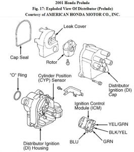
Ignition Control Module (ICM) Input Test (Prelude)
1. Turn ignition off. Remove distributor cap, rotor, leak cover and cap seal. Disconnect wires from ICM. See Fig. 17 . Turn ignition on. Check for voltage between body ground and Black/Yellow wire. If battery voltage exists, go to next step. If battery voltage does not exist, check for open in Black/Yellow wire between ignition switch and ICM.
2. Ensure ignition is on. Check for voltage between body ground and Green wire. See Fig. 17 . If battery voltage exists, go to next step. If battery voltage does not exist, check ignition coil operation. Replace ignition coil as necessary. If ignition coil is okay, check for open in Green wire between ICM and ignition coil.
3. Turn ignition switch off. Disconnect PCM connector "A" (32-pin connector). Check for continuity of Yellow/Green wire between PCM connector "A" (32-pin connector) terminal No. 20 and ICM. If continuity exists, go to next step. If continuity does not exist, repair open in Yellow/Green wire.
4. Check for continuity between body ground and Yellow/Green wire. If continuity does not exist, go to next step. If continuity exists, check for short to ground in Yellow/Green wire.
5. Reconnect PCM connector "A" (32-pin connector). Disconnect instrument cluster 16-pin connector. Check continuity of Blue wire between ICM and tachometer. If continuity exists, go to next step. If continuity does not exist, repair open in Blue wire between ICM and tachometer.
6. Check for continuity between body ground and Blue wire. If continuity exists, check for short to ground in Blue wire. If continuity does not exist, wiring is okay at this time. Replace ICM. Reconnect instrument cluster 16-pin connector.
Sunday, May 3rd, 2009 AT 5:57 PM