Can be the headlamp switch, the GEM, or the multi-function switch or wiring/fuses, scan it for "B" codes before you begin this will pin point the area of the fault.
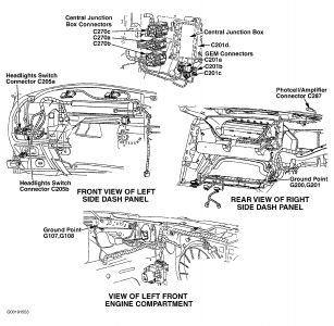
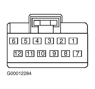
TEST C: HEADLIGHTS INOPERATIVE WITH AUTOLAMPS ON 1. Turn headlight switch to ON position. If headlights operate, go to next step. If headlights do not operate, repair headlight system. See HEADLIGHTS in appropriate SYSTEM WIRING DIAGRAMS article in ELECTRICAL. 2. Turn ignition switch to LOCK position. Disconnect headlight switch 12-pin harness connector C205a, located on left side of dash panel. See Fig. 1 . Turn ignition switch to RUN position.
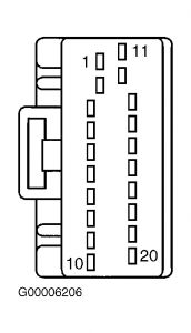
Using WDS or NGS tester, command headlights ON. Measure voltage between ground and headlight switch harness connector C205a terminal No. 9 (Red/Yellow wire). See Fig. 4 . See WIRING DIAGRAMS . If any voltage exist, go to next step. If voltage does not exists, go to step 6 . 3. Turn ignition switch to LOCK position.
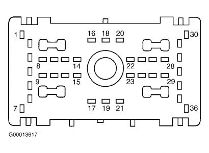
Disconnect Central Junction Box (CJB) 36-pin harness connector C270b, located under left side of instrument panel. See Fig. 1 . Measure resistance between headlight switch harness connector C205a terminal No. 9 and CJB harness connector C270b terminal No. 32 (Red/Yellow wire). See Fig. 4 and Fig. 7 . See WIRING DIAGRAMS . If resistance is less than 5 ohms, reconnect CJB harness connector C270b and go to next step. If resistance is 5 ohms or more, repair open circuit in Red/Yellow wire between headlight switch and CJB.
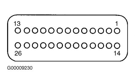
After repair, clear DTCs and test system for normal operation. 4. Remove fuse No. 29 (15-amp) from Central Junction Box (CJB), located under left side of instrument panel. See Fig. 1 . Disconnect GEM harness connector C201d. See Fig. 8 . Turn ignition switch to RUN position. Measure voltage between ground and GEM harness connector C201d terminal No. 25 (CJB side). See Fig. 8 . See WIRING DIAGRAMS . If any voltage exists, repair or replace CJB as necessary. If no voltage exists, install fuse No. 29 and go to next step.
After repair, clear DTCs and test system for normal operation. 5. Disconnect CJB 36-pin harness connector C270b, located under left side of instrument panel. See Fig. 1 . Connect a 10-amp fused jumper wire between ground and GEM harness connector C201d terminal No. 25 (CJB side). See Fig. 8 . Measure resistance between ground and CJB harness connector 270b terminal No. 32 (CJB side). See Fig. 7 . See WIRING DIAGRAMS . If resistance is less than 5 ohms, reconnect all harness connectors and go to next step. If resistance is 5 ohms or more, repair or replace CJB as necessary. After repair, clear DTCs and test system for normal operation.
6. Disconnect all GEM harness connectors. Inspect for corrosion or pushed out pins. Repair or replace connectors terminals as necessary. See WIRING DIAGRAMS . Reconnect all GEM harness connectors, ensuring they are connected correctly. Operate system and verify if concern is still present. If concern is still present, replace GEM. See GENERIC ELECTRONIC MODULE under REMOVAL & INSTALLATION. If concern is not present, system is operating correctly at this time. After repair, clear DTCs and test system for normal operation.
Fig. 7: Identifying Central Junction Box Harness Connector C270b Terminals Courtesy of FORD MOTOR CO. Fig. 8: Identifying Generic Electronic Module Harness Connector C201d Terminals Courtesy of FORD MOTOR CO. NOTE: Perform all voltage and resistance tests using a Digital Volt-Ohm Meter (DVOM) with a minimum 10-megohm input impedance, unless stated otherwise in test procedure. Use an ohmmeter to isolate wiring harness shorts or opens. Page 1 of 1 AUTOLAMP SYSTEMS -2001 Ford Taurus SE 9/6/2008
Saturday, August 15th, 2020 AT 10:56 AM
(Merged)


