TEST A - INSTRUMENT CLUSTER DISPLAY(S) INOPERATIVE OR ERRATIC
1.Check METER fuse. See Fig. 4 . If fuse is okay, go to step 4). If fuse is blown, go to next step.
2.Turn ignition off. Replace 10A (15A wagon only) METER fuse. Turn ignition on and inspect fuse. If fuse fails again, go to next step. If fuse does not fail, go to step 4).
3.Turn ignition off. Remove instrument cluster. See INSTRUMENT CLUSTER under REMOVAL & INSTALLATION. Disconnect all (3) instrument cluster electrical connectors. Disconnect low coolant level warning sensor. Remove METER fuse. Measure resistance between bottom terminal (Black/Yellow wire) of METER fuse holder and ground. Resistance should be greater than 10 k/ohms. If resistance is greater than 10 k/ohms, go to next step. If resistance is less than 10 k/ohms, repair Black/Yellow wire(s) for short to ground. See WIRING DIAGRAMS .
4.Turn ignition ON. Measure voltage between ground and top terminal of METER fuse holder. Voltage should be greater than 10 volts. If voltage is greater than 10 volts, go to next step. If voltage is less than 10 volts, repair power feed for METER fuse. See WIRING DIAGRAMS .
5.Turn ignition off. Remove instrument cluster. See INSTRUMENT CLUSTER under REMOVAL & INSTALLATION. Disconnect all (3) cluster electrical connectors. Turn ignition on. Measure voltage between ground and Black/Yellow wire(s) on each instrument cluster harness connector. Voltage should be greater than 10 volts at each Black/Yellow wire. If voltage is greater than 10 volts, go to next step. If voltage is less than 10 volts, repair Black/Yellow wire(s) in question. See WIRING DIAGRAMS .
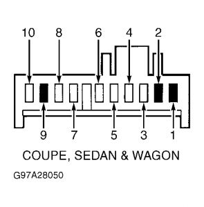
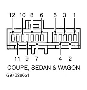
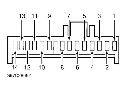
6.Turn ignition OFF. Measure resistance between ground and instrument cluster harness connector C1, terminal No. 5 (Black/Green wire). See Fig. 5 . Resistance should be less than 5 ohms. Measure resistance between ground and instrument cluster harness connector C2, terminal No. 7 (Blue wire). See Fig. 6 . Resistance should be less than 5 ohms. Measure resistance between ground and instrument cluster harness connector C3, terminals No. 7 (Black/Green wire) and No. 11 (Black wire). See Fig. 7 . Resistance should be less than 5 ohms.
7.If resistance is less than 5 ohms on all wires, replace instrument cluster printed circuit and gauge contact clips. See PRINTED CIRCUIT under REMOVAL & INSTALLATION. If any resistance is more than 5 ohms, repair circuits in question. See WIRING DIAGRAMS .
Fig. 5: Identifying Instrument Cluster Harness Connector C1 Courtesy of FORD MOTOR CO.
Fig. 6: Identifying Instrument Cluster Harness Connector C2
Courtesy of FORD MOTOR CO.
Fig. 7: Identifying Instrument Cluster Harness Connector C3
Courtesy of FORD MOTOR CO.


To do just the bulbs if that's all it needs follow this procedure.
INSTRUMENT PANEL - ANALOG -1997 Ford Escort LX
Removal & Installation
1.Remove instrument cluster. See INSTRUMENT CLUSTER . Remove 5 instrument cluster mask screws and remove mask and lens.
CAUTION:Handle gauges and components with care. Make no attempt to adjust indicator needles.
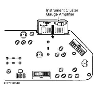
2.By pulling straight out, remove temperature gauge, fuel gauge, speedometer and tachometer (if equipped). Depress tang and remove instrument cluster gauge amplifier from rear of cluster. 3.Remove indicator and illumination bulbs from rear of instrument cluster. Remove gauge contact clips from rear of cluster by compress-ing clip ends together and pulling out. Discard clips. Carefully remove printed circuit from rear of instrument cluster. To install, reverse removal procedure using NEW gauge contact clips.
CAUTION:When removing gauge contact clips, DO NOT damage instrument cluster printed circuit.
9/21/2008

Of course all you want to do is the bulbs, so do just them, leave the gauges and print circuit alone.
Thanks for using 2Carpros.com
Sunday, July 26th, 2020 AT 10:57 AM
(Merged)


