Welcome to 2CarPros.
Either the clutch master cylinder has failed or the slave cylinder. Also, the pressure line between the two may have failed. First, check for evidence of leaks. Most times, you will see which one is bad. Here are directions for both in case you determine which is bad. Considering it worked better for a short time when you worked on the master cylinder, that is my first suspect.
Here are directions for slave replacement. I am hoping this isn't the cause because the trans needs removed to replace it.
PROCEDURES
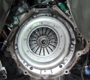
Clutch Actuator Cylinder Replacement
Removal Procedure
picture 1
1. Disconnect the clutch master cylinder line from the transaxle by removing the C-clip.
2. Remove the transaxle.
3. Remove the clutch actuator cylinder bolts from the transaxle.
4. Remove the clutch actuator cylinder.
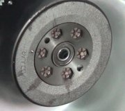
Installation Procedure
pic 2
Important: Excessive amounts of lubricant on the input shaft splines can contaminate the clutch disc and cause clutch shudder.
1. Lightly lubricate the inside diameter of the bearing with input shaft lubricant P/N 21005995 or equivalent.
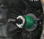
2. Install the clutch actuator cylinder (1) to the transaxle.
Notice: Refer to Fastener Notice in Cautions and Notices.
3. Install the clutch actuator cylinder bolts.
- Tighten the bolts to 10 Nm (89 inch lbs.).
4. Install the transaxle.
Pic 3
5. Connect the clutch master cylinder line to the transaxle by pushing it in until it seats.
6. Bleed the clutch hydraulic system.
______________________________________________
PROCEDURES
Clutch Master Cylinder Replacement
Removal Procedure
pic 4
1. Clean the clutch fluid reservoir cap and area around the cap.
2. Remove the clutch fluid reservoir cap and remove enough brake fluid to clear a passage to the clutch master cylinder.
3. Remove the clutch pedal retainer.
4. Remove the clutch master cylinder pushrod from the clutch pedal assembly, 1st design.
Pic 5
5. Remove the clutch master cylinder pushrod from the clutch pedal assembly, 2nd design.
Pic 6
Notice: Refer to Brake Fluid Effects on Paint and Electrical Components Notice in Cautions and Notices.
6. Place a shop towel under the clutch master cylinder in order to catch any fluid loss.
7. Using a pick tool on the strut tower side, disconnect the clutch line from clutch master cylinder.
8. Cap the reservoir and hydraulic lines in order to prevent fluid loss and contamination.
Pic 7
Important: Do not damage the pushrod boot when sliding it through the front of the dash.
9. Remove the clutch master cylinder mounting nuts and slide the clutch fluid reservoir up and out.
Installation Procedure
pic 8
Important: Do not damage the pushrod boot when sliding it through the front of the dash.
1. Uncap the fluid reservoir and hydraulic lines.
Notice: Refer to Fastener Notice in Cautions and Notices.
2. Slide the clutch fluid reservoir into the mounting slot and install the clutch master cylinder mounting nuts.
- Tighten the nuts to 23 Nm (17 ft. Lbs.).
Pic 9
3. Install the clutch master cylinder pushrod to the clutch pedal assembly, 1st design.
4. Install the clutch pedal retainer.
Pic 10
5. Install the clutch master cylinder pushrod to the clutch pedal assembly, 2nd design.
Pic 11
6. Remove the shop towel and discard into a suitable container.
7. Connect the clutch line to the clutch master cylinder.
Pic 12
8. Connect the clutch master cylinder pushrod to the clutch pedal.
9. Install the clutch pedal retainer, nuts and bolts.
10. Bleed the clutch hydraulic system.
_______________________
Here are the most updated procedures for bleeding the system.
This procedure can be used anytime air is introduced into the hydraulic system. Following this procedure may also reduce the number of unnecessary parts replaced for low clutch pedal reserve and high shift effort.
Verify that all the lines and fittings are dry and secure.
Clean the dirt and grease from the reservoir cap in order to ensure that no foreign substances enter the system.
Remove the reservoir cap.
Fill the reservoir to the proper level with the required fluid.
Attach the J 43485 (Adapter) to the J 35555 (Mity Vac), or equivalent.
Brake fluid will deteriorate the rubber on J 43485. Use a clean shop cloth to wipe away the fluid after each use.
Place and hold the adapter on the reservoir filler neck to ensure a tight fit. In some cases, the adapter will fit into the reservoir opening.
Apply a vacuum of 51-68 kPa (15-20 hg) and remove the adapter.
Refill the reservoir to the proper level.
Repeat Steps 6 and 7.
If needed, refill the reservoir and continue to pull a vacuum until no more bubbles can be seen in the reservoir or until the fluid level no longer drops.
The vehicle will move if started in gear before the Actuator Cylinder is refilled and operational. Start the vehicle the first time in neutral to help prevent personal injury from vehicle movement and see if the transmission will shift easily into gear.
Pump the clutch pedal until firm (to refill actuator cylinder).
Add additional fluid if needed.
Test drive vehicle to ensure proper operation.
++++++++++++++++++++++++++++++++++++++++++++++++++++
Let me know if this helps.
Take care,
Joe
Images (Click to make bigger)
Sunday, May 12th, 2019 AT 9:12 PM


