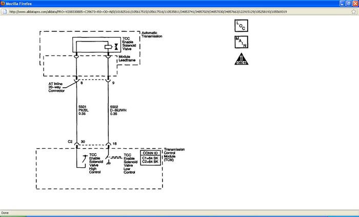
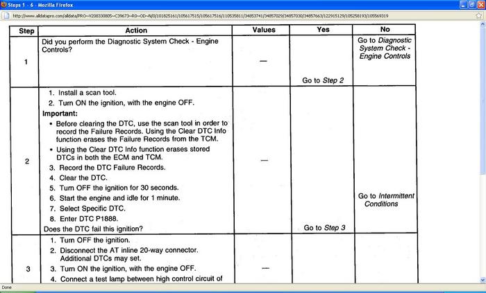
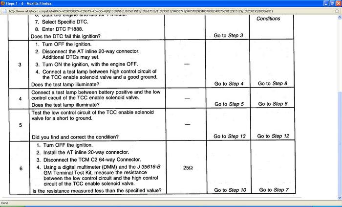
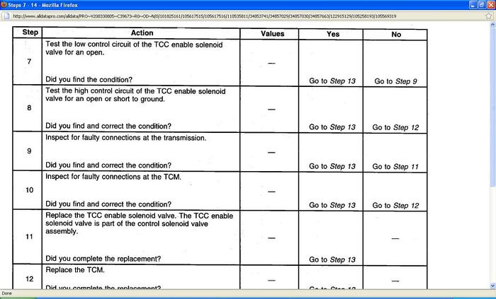
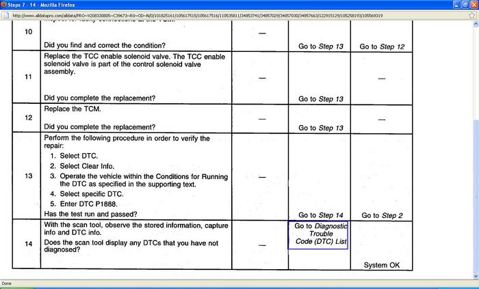
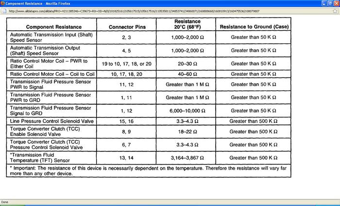
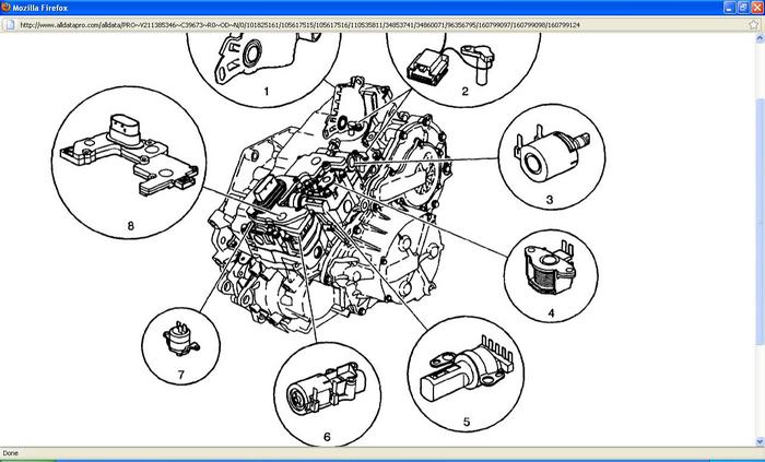
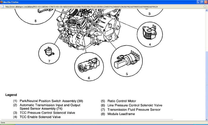
The P0717 code is for the input speed sensor I posted the code description and trouble tree for it. The code P0701 I posted the code description and trouble tree let me know what you find.
DTC P0717
Circuit Description
The input speed sensor (ISS) is a permanent magnet generator. The ISS sensor is mounted inside the transmission, under the control valve body cover. The sensor faces the input shaft speed sensor reluctor ring assembly. As the reluctor ring assembly rotates, an AC voltage is induced and transmitted to the transmission control module (TCM). The AC voltage level and the number of pulses increase as the speed of the reluctor ring assembly increases. The TCM converts the AC voltage into a digital signal. The TCM uses the input speed signal to help determine line pressure, transmission ratio control patterns and TCC apply pressure and timing.
If the TCM detects no input shaft speed when there is vehicle speed in a drive gear range, DTC P0717 sets. DTC P0717 is a type A DTC.
Conditions for Running the DTC
* No OSS DTCs P0722 or P0723.
* No transmission range switch DTCs P0705, P1756, or P1758.
* No engine torque DTC P1779.
* The engine speed is greater than 500 RPM for 5 seconds.
* The selected range is not PARK or NEUTRAL.
* The engine torque is between 30 - 300 Nm (22 - 221 ft. Lbs.).
* The transmission output shaft speed is 400 RPM or greater.
Conditions for Setting the DTC
The transmission input shaft speed is 100 RPM or less for 5 seconds.
Action Taken When the DTC Sets
* The TCM requests the ECM to illuminate the malfunction indicator lamp (MIL).
* The TCM moves the speed ratio towards a target ratio and then freezes ratio changes.
* The TCM discontinues use of the closed loop ratio control algorithm. This causes the speed ratio to be defaulted and possibly not accurate. The resulting open loop control may or may not provide optimum ratio performance.
* The TCM commands maximum pressure to the input clutch.
* The TCM calculates input shaft speed from the output shaft speed sensor and the commanded speed ratio.
* The TCM commands a line pressure increase for all operating conditions.
* The TCM freezes garage shift transmission adaptive functions.
* The TCM freezes main line pressure transmission adaptive functions.
* The ECM records the operating conditions when the Conditions for Setting the DTC are met. The ECM stores this information as Freeze Frame and Failure Records.
* The TCM records the operating conditions when the Conditions for Setting the DTC are met. The TCM stores this information as Failure Records.
* The TCM stores DTC P0717 in TCM history.
Conditions for Clearing the MIL/DTC
* The ECM turns OFF the MIL after the third consecutive drive trip in which the TCM does not send a MIL illumination request.
* A scan tool can clear the MIL/DTC.
* The TCM clears the DTC from TCM history if the vehicle completes 40 warm-up cycles without an emission related diagnostic fault occurring.
* The TCM cancels the DTC default actions when the ignition switch is OFF long enough in order to power down the TCM.
Diagnostic Aids
* Ensure the ISS is properly installed in the transmission.
* Inspect the connectors at the TCM, the transmission, and all other circuit connecting points for an intermittent condition.
* Inspect the circuit wiring for an intermittent condition.
Test Description
The numbers below refer to the step numbers on the diagnostic table.
3. The resistance measurement will not change if either the ISS high signal circuit or the ISS low signal circuit, but not both, is shorted to ground. The vehicle speed detector in the TCM and the ISS are matched in such a way that an open or a short to ground in the ISS low signal circuit will not usually cause a loss of speed signal or a DTC P0717 to set.
6. This step isolates the short between the ISS and the wiring.
12. Refer to the latest procedures for TCM reprogramming.
DTC P0701
Circuit Description
Modules that are connected to the CAN serial data circuits monitor each other for serial data communications during normal vehicle operation. Operating information and commands are exchanged among the modules. The modules have prerecorded information about messages that are exchanged on the serial data circuits. The supervised and periodic messages are used by the receiving module as an availability, and state of health indicator from the transmitting module. If the engine control module (ECM) detects a message that indicates a loss of communication, invalid or corrupted serial data, or an active malfunction in the transmission control module (TCM), that requires ECM intervention, DTC P0701 sets.
DTC Descriptor
This diagnostic procedure supports the following DTC:
* DTC P0701 Transmission Control System Performance.
Conditions for Running the DTC
* The ignition is in any of the following positions:
* Unlock
* Accessory
* Run
* Crank
* OFF, but the ECM has not powered down
* The ignition 1 voltage is more than 9 Volts.
* Depending on the ignition mode, an engine run time of more than 1-3 seconds is required for certain messages.
* This DTC runs continuously within the enabling conditions.
Conditions for Setting the DTC
* The TCM has an active malfunction and is requesting ECM intervention. OR
* Loss of communication between the ECM and the TCM. OR
* Invalid serial data between the ECM and the TCM. OR
* Loss of the state of health message between the ECM and the TCM. OR
* An active vehicle speed malfunction in the TCM.
Action Taken When the DTC Sets
* The control module illuminates the malfunction indicator lamp (MIL) when the diagnostic runs and fails.
* The control module records the operating conditions at the time the diagnostic fails. The control module stores this information in the Freeze Frame/Failure Records.
Conditions for Clearing the MIL/DTC
* The control module turns OFF the malfunction indicator lamp (MIL) after 3 consecutive ignition cycles that the diagnostic runs and does not fail.
* A current DTC, Last Test Failed, clears when the diagnostic runs and passes.
* A history DTC clears after 40 consecutive warm-up cycles, if no failures are reported by this or any other emission related diagnostic.
* Clear the MIL and the DTC with a scan tool.
Diagnostic Aids
A module which loses power during the current ignition cycle, will have a Loss of Communication DTC set by the other modules that require information from the failed module.
If the TCM, using a faulty manifold absolute pressure (MAP) signal, calculates an invalid torque value, the TCM will command ECM intervention and set a DTC P0701.
If there is an active vehicle speed malfunction in the TCM, DTC P0701 will set.
If the ECM's ignition 1 voltage circuit, that is used to wake up the module is open, the TCM may set a DTC U2105 and request a limp-home mode, which will result in DTC P0701 also being set.
Saturday, March 26th, 2011 AT 6:30 PM
