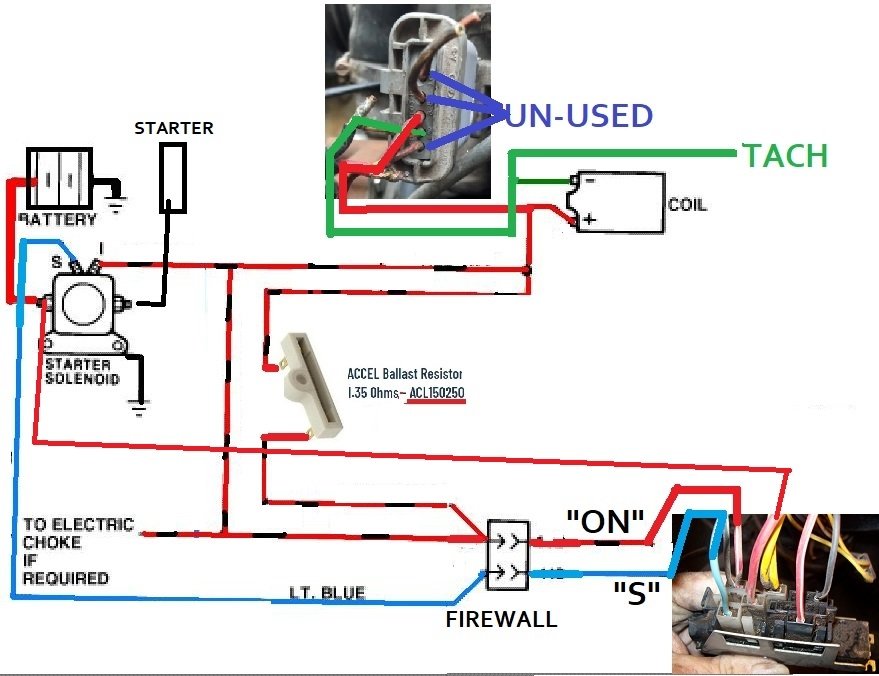
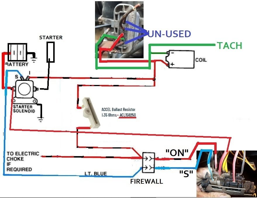
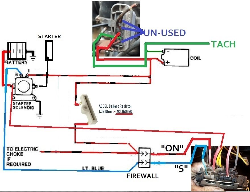
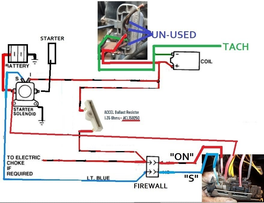
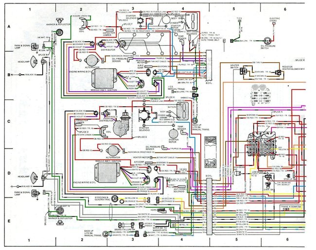
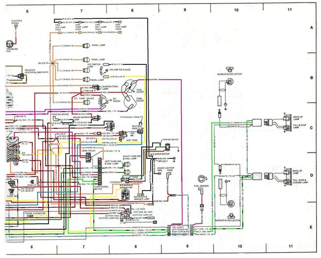
Just so you have this reference, you can follow wires, there are not any fuses in the wires you mentioned. Below is a 1979, I had to sort of modify it so it could be understood. Here's the explanations that might make it clearer.
Most '76-'86 CJ's have a lot of common wiring. This is good one to use for these years.
Yep, I scanned a 2 piece diagram from a paper manual.
I took it to "microsoft paint" and colored the wires the best that I could.
Here's things you must know to read it accurately:
A) along each wire [maybe several places] is "wording" or a "label" with the size and color(s) for the wire.
B) a "white wire" will show up black!
C) a solid color wire will be labeled like this "12a red 10".
12a is a numerical reference # / red is the color / 10 is the gauge of the wire.
Here's the part that will be sorta confusing.
D) some wires have tracer stripes, the manual did not tell what color the stripe was (on any of the striped wires) they are labeled like this "8a grn / tr-18".
8a being a numerical reference # / grn, meaning green wire / tr meaning it has a colored stripe down the wire (stripe color unknown )
So so so so so to make it ez to know/ see there was a wire with a tracer stripe, I simply put black dashes along those wires (exception was on the white wires)
But still, the actual stripe color will not be known till you find the actual wire, where it starts or ends on the jeep (sorry! It does work for me!)
E) illusions! Sometimes it may look like a wire stops, an example might be 3 red wires going into a splice, well one of 'em has a "label" right at the splice (the red color does not go thru the label)
So 2 "red wires" hit the splice along with a "label"- at a glance you only see 2 red wires when there are actually 3. Just be aware of the label "still being" a wire. You can see one example of this in one place where the ignition module gets it's power at "splice l"
My 2 diagrams overlap about on the line between "5 and 6" of the outer rim reference lines. To me it looks like the right side diagram fits better on top of the left side diagram at the overlap. You will notice the fuse box is the area of the overlap.
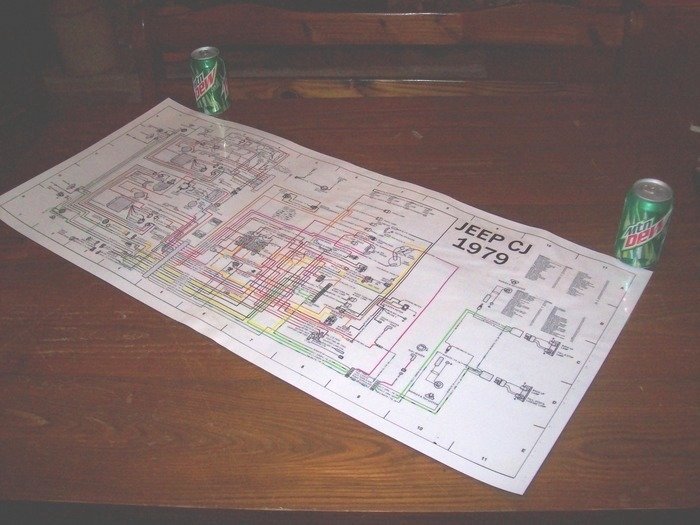
I sent my 2 parts to the office store via email, had 'em blown up, I taped them together at the overlap, then the office store laminated the one big diagram for me. It's so much easier to read it now!
I'm not perfect, you will find some mistakes!
The Medic
Images (Click to make bigger)
Tuesday, March 31st, 2020 AT 6:16 PM
