Hey Kyle,
DTC P0153-A: O2S 2/1 SLOW RESPONSE
NOTE:
For connector terminal ID, see CONNECTOR IDENTIFICATION. For wiring diagram, see WIRING DIAGRAMS article.
The Signal Circuit is the Light Green/Red
The Ground Circuit is the Black/Orange
1. For O2 sensor/model identification see O2S 2/1 CONNECTOR WIRE IDENTIFICATION (HARNESS SIDE) table. This DTC sets if O2S 2/1 signal voltage is switching from less than.27 volts to more than.62 volts fewer times than required. Possible causes are: exhaust leak, fuel contamination, O2S failure, faulty electrical connections or O2S heater failure. Go to next step.
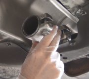
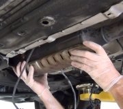
2. Start engine. Check for exhaust system leaks between engine and catalytic converter. If no exhaust system leaks are found, go to next step. If exhaust system leaks are found, repair exhaust system as necessary. Perform TEST VER-5A: ROAD TEST FOR OBD-II TROUBLE CODES.
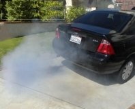
3. Check exhaust for excessive smoke from coolant or oil consumption. If coolant or oil consumption is not present, go to next step. If coolant or oil consumption is present, repair engine mechanical failure as necessary. Replace O2S 2/1. Perform TEST VER-5A: ROAD TEST FOR OBD-II TROUBLE CODES.
4. Using scan tool, read DTCs. If Global Good Trip displayed is zero, go to step 6. If Global Good Trip displayed is not zero, using a DVOM, backprobe O2S 2/1 signal circuit between O2S 2/1 connector (harness side) and PCM connector terminal No. 29. See O2S 2/1 CONNECTOR WIRE IDENTIFICATION (HARNESS SIDE) table and PCM CONNECTOR WIRE IDENTIFICATION table. If voltage drop is less than.10 volts, go to next step. If voltage drop is.10 volts or more, repair high resistance in O2S 2/1 signal circuit. Perform TEST VER-5A: ROAD TEST FOR OBD-II TROUBLE CODES.
5. Using a voltmeter, backprobe O2S 2/1 ground circuit between O2S 2/1 connector (harness side) and PCM connector terminal No. 27. See O2S 2/1 CONNECTOR WIRE IDENTIFICATION (HARNESS SIDE) table and PCM CONNECTOR WIRE IDENTIFICATION table. If voltage drop is less than.10 volts, replace O2S 2/1. Perform TEST VER-5A: ROAD TEST FOR OBD-II TROUBLE CODES. If voltage drop is.10 volts or more, repair high resistance in O2S 2/1 ground circuit.
6. Using a DVOM, backprobe O2S 2/1 signal circuit between O2S 2/1 connector (harness side) and PCM connector terminal No. 29. See O2S 2/1 CONNECTOR WIRE IDENTIFICATION (HARNESS SIDE) table and PCM CONNECTOR WIRE IDENTIFICATION table. Observe DVOM while wiggling wiring harness. If voltage drop is less than.10 volts, go to next step. If voltage drop is.10 volts or more, repair high resistance on O2S 2/1 signal circuit. Perform TEST VER-5A: ROAD TEST FOR OBD-II TROUBLE CODES.
7. Using scan tool, read FREEZE FRAME data. Ensure hex code matches DTC on scan tool. Hex code should be 7A. If hex code corresponds to scan tool display, go to next step. If hex code does not correspond to scan tool display, repair DTC using FREEZE FRAME data. Perform TEST VER-5A: ROAD TEST FOR OBD-II TROUBLE CODES.
8. Reconnect O2S 2/1 connector. Drive vehicle under FREEZE FRAME data conditions. Using scan tool, read DTCs. If Global Good Trip displayed is zero, perform test procedure again. After performing test procedure again, perform TEST VER-5A: ROAD TEST FOR OBD-II TROUBLE CODES. If Global Good Trip displayed is not zero, DTC is not present at this time. Using scan tool, erase DTCs. Perform TEST VER-5A: ROAD TEST FOR OBD-II TROUBLE CODES.
Will Post more tommorrow have to go sick kids.
.
Tuesday, February 9th, 2010 AT 9:18 PM


