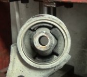
It is an involved process. However, I did find directions for you to follow if you want to try it on your own. Rust and corrosion see to be the biggest problem.
Here are the directions. Let me know if you have other questions:
Use only the proper tools for separating the ball joint from the steering knuckle. If you don't use the correct tools, you could damage the ball joint and seal.
1. Raise and safely support the vehicle. Position a jackstand under the engine cradle/frame and lower the vehicle so the weight of the vehicle rests on the jackstand and not the control arms. The control arms must hang free.
2. Remove the tire and wheel assembly.
3. Disconnect the stabilizer shaft-to-control arm bolt.
4. Separate the ball joint from the steering knuckle and the control arm, as outlined earlier in this section.
5. Unfasten the control arm mounting bolts, then remove the control arm from the engine cradle/frame.
To install:
6. Position the control arm to the engine cradle. Install the bolts, washers nuts as shown in the accompanying figure, but do not tighten the control arm bolts at this time. The weight of the vehicle must be supported by the control arms so the vehicle design trim heights are obtained before tightening the control arm mounting nuts.
7. Install the stabilizer shaft to the control arm.
8. Connect the ball joint to the steering knuckle.
9. Tighten the stabilizer shaft link nut to 13 ft. Lbs. (2 Nm). Install the ball joint slotted nut and tighten to 88 inch lbs. (10 Nm). Then tighten the nut an additional 120 ° (2 flats on the nut) during which a torque of 41 ft. Lbs. (55 Nm) must be achieved.
10. Install a new cotter pin. To align the slot, if necessary, tighten the nut up to one more flat. NEVER loosen the nut to install the pin.
11. For 1987-92 vehicles, perform the following steps:
A. Raise the vehicle so the weight of the vehicle is supported by the control arm.
The weight of the vehicle must be supported by the control arms when tightening the control arm mounting nuts.
B. Tighten the rear control arm mounting nut to 88 ft. Lbs. (120 Nm) and the front mounting nut to 144 ft. Lbs. (195 Nm).
C. Raise the vehicle and remove the jackstand.
12. Replace the tire and wheel assembly.
13. Carefully lower the vehicle, then tighten the wheel lug nuts to 100 ft. Lbs. (136 Nm).
14. For 1993-99 vehicles, perform the following steps to check the trim height and tighten the control arm retainers.
A. Make sure the vehicle is parked on level ground, check the tire pressure and the fuel level. The fuel tank should be full.
B. There should be no extra weight in the passenger compartment or trunk; the trunk must be empty except for the spare tire and jack.
C. If equipped with Electronic Level Control (ELC), make sure it is operating properly.
D. Place the front seat to the rear position.
E. Bounce the vehicle 3 times at the front and rear of normalize the suspension.
F. Make measurements D, Z, J and K, as shown on the accompanying illustration.
G. Compare the measurements taken with those listed below. Maximum variation side-to-side and front-to-rear is 3 / 4 in. (19mm).
15.D - 2 11 / 1 -3 7 / 1 in. (68-88mm)
16.Z - 1 15 / 1 -2 3 / 7 in. (50-70mm)
17.J - 9-9 13 / 1 in. (229-249mm)
18.K - 9 9 / 32 -10 1 / 1 in. (236-256mm)
Fig. Fig. 2: On 1993-99 vehicles, you MUST measure the trim height before tightening the control arm retainer
A. Tighten the FRONT control arm mounting nut to 140 ft. Lbs. (190 Nm).
B. Tighten the REAR control arm mounting nut to 91 ft. Lbs. (123 Nm).
Wednesday, November 4th, 2009 AT 10:40 AM


