Hi,
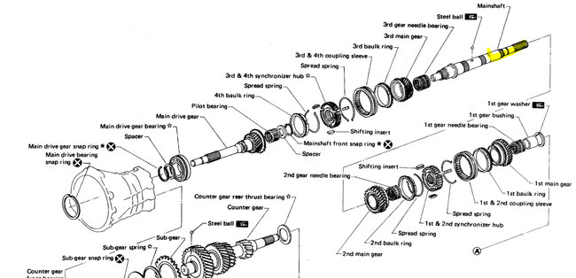
The transmission needs to be removed and inspected. I have a feeling the input shaft is broken. Since it's not even turning in 4wd (front or rear) there has to be a disconnection. The only other thing I can think of is if the shifter is not properly installed and is stuck in neutral (trans or transfer case)
Here are the directions for removal. This is what I would do, but that is your call. The attached pics correlate with the directions.
_______________________
1986 Nissan-Datsun Truck D21 Hardbody 4WD V6-2960cc 3.0L SOHC (VG30i)
Transmission Removal
Vehicle Transmission and Drivetrain Manual Transmission/Transaxle Service and Repair Procedures Transmission Removal
TRANSMISSION REMOVAL
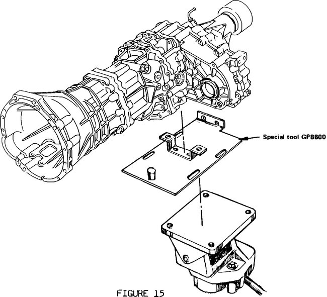
WARNING Do not remove transmission/transfer case without Special Tool #GP8600 (available through a dealership) or equivalent. Use a transmission jack with at least 500 lb. Capacity. Transmission/transfer case assembly weighs approximately 300 lbs. Use extreme caution when handling.
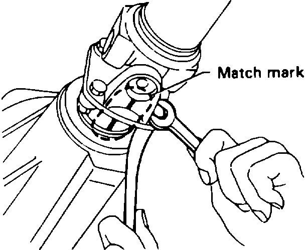
FIGURE 1
NOTE: All bolt specifications shown are socket/wrench size.
1. Disconnect the battery cables (negative cable first).
2. Raise the vehicle on a frame type hoist.
3. Drain the oil from the transmission.
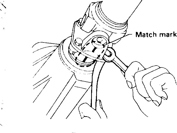
4. Place match marks on the rear propeller shaft/rear axle flanges (Figure 1).
5. Mark both front propeller shaft flanges (at front axle and transfer case) (Figure 1).
6. Remove the four (17 mm) nuts and bolts between the rear propeller shaft and rear axle (breaker bar or impact wrench required) (Figure 1).
FIGURE 2
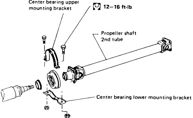
7. THIS STEP IS FOR LONG WHEELBASE VEHICLES ONLY. Remove the two propeller shaft center bearing bracket bolts (17 mm) (Figure 2).
FIGURE 3
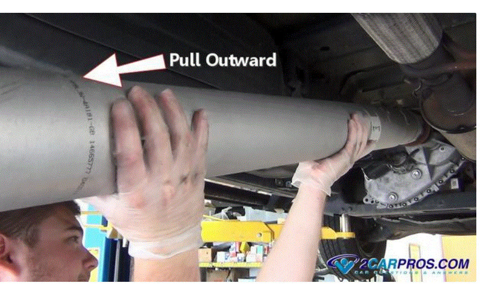
8. Remove the rear propeller shaft from the vehicle. Plug the transfer case with a rag to avoid oil loss.
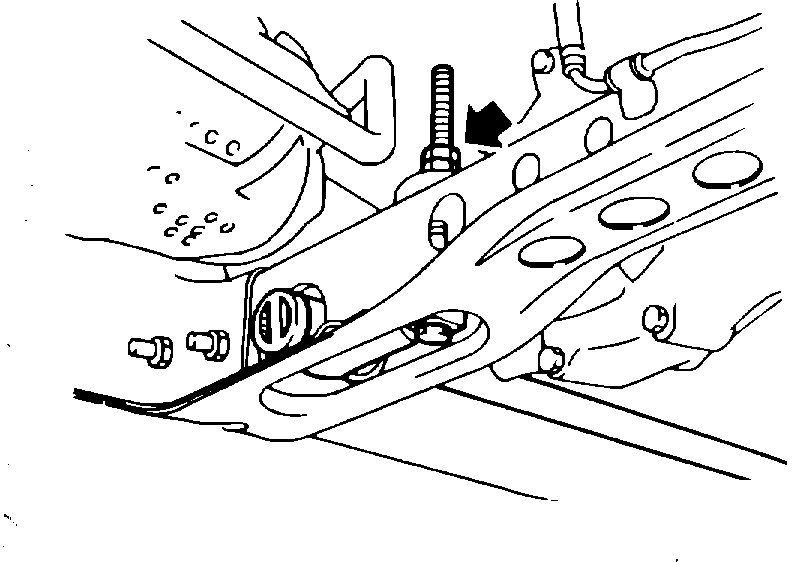
9. Loosen (do not remove) both torsion bar adjusting bolts (19 mm) (Figure 3).
FIGURE 4
10. Remove the front torsion bar mounts (two 14 mm and one 19 mm nut per side) (Figure 4). Remove the two 10 mm vent line screws in cross member.
FIGURE 5
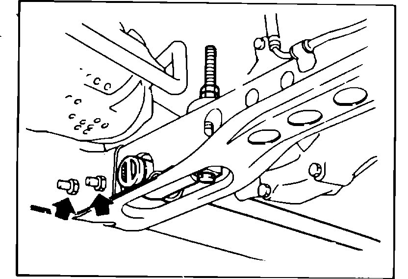
11. Remove the two bolts (17 mm) on each side of torsion bar cross member (Figure 5).
12. Remove the cross member and torsion bars as a unit.
FIGURE 6
13. Remove the exhaust system as follows:
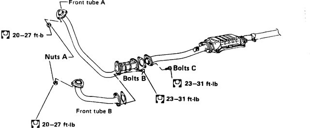
a. Disconnect front tubes A and B from each exhaust manifold (3 [17 mm] nuts on each side) (Nuts A in Figure 6).
A. Disconnect front tube B from tube A (2 [17 mm] bolts) (Bolts B in Figure 6).
A. Remove the two bolts (17 mm) between front tube A and front tube C (Bolts C in Figure 6).
A. Remove front tubes A and B from the vehicle (Figure 6).
14. Remove exhaust bracket from transfer case (two 12 mm bolts).
FIGURE 7
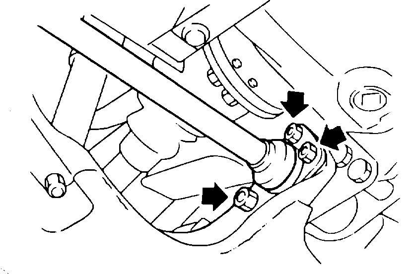
15. Remove the four bolts (14 mm) from both front propeller shaft flanges (Figure 7).
16. Remove the front propeller shaft from the vehicle.
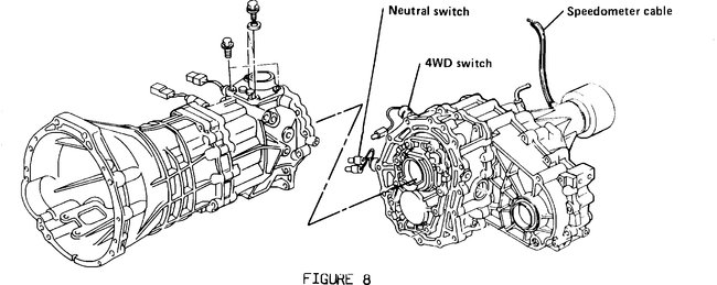
FIGURE 8
17. Remove the speedometer cable and vent tube from the transfer case. Disconnect the neutral switch and 4WD switch harness connectors from the main harness (Figure 8).
FIGURE 9
18. Remove the transfer control lever from the transfer outer shift lever (Figure 9).
FIGURE 10
19. Disconnect the transfer case linkage assembly (two 12 mm bolts on each bracket) from the transmission (Figure 10).
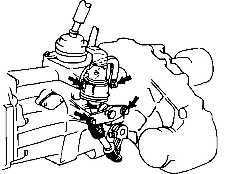
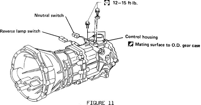
FIGURE 11
20. Using an open end wrench, remove the two (13 mm) and two (12 mm) bolts from the shifter control housing (Figure 11). Loosen the control housing from the transmission.
21. Disconnect the neutral switch and reverse lamp switch harness connectors from the transmission (Figure 11).
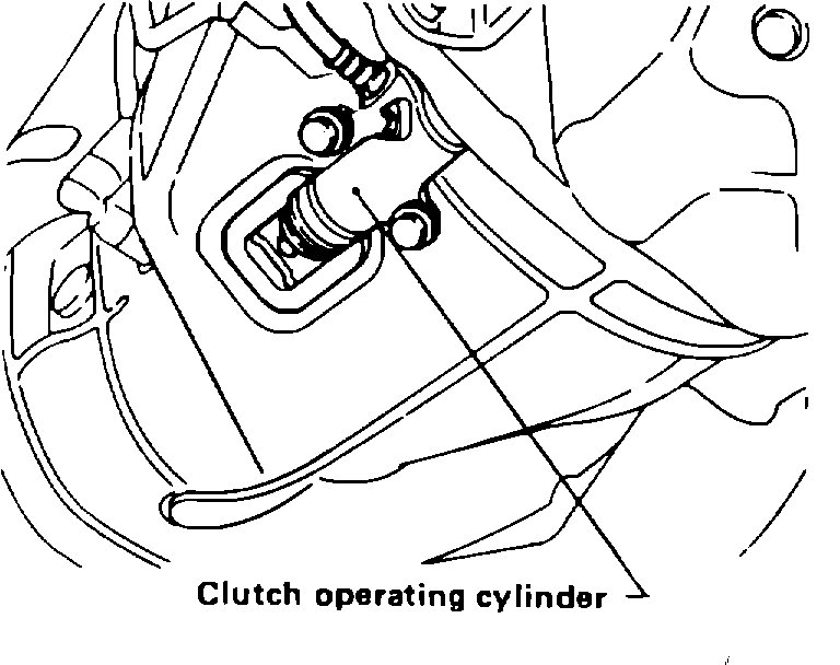
FIGURE 12
22. Remove the clutch operating cylinder (two 14 mm bolts) (Figure 12).
23. Remove the starter (two 14 mm bolts).
24. Remove the front under guard (six 10 mm bolts and two plastic rivets).
25. Remove the O2 sensor harness from clips on transmission.
26. Disconnect the vent tube from the transmission.
27. Support the transfer case tail shaft with a transmission jack.
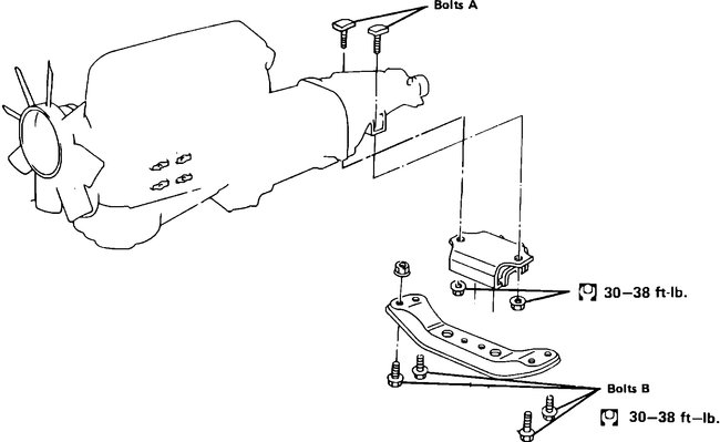
FIGURE 13
28. Remove the transfer case under guard (two 12 mm and two 14 mm bolts).
29. Remove the two bolts (17 mm) between transmission mount and transmission (Bolts A in Figure 13).
30. Remove the four bolts (17 mm) between the transmission cross member and vehicle frame (Bolts B in Figure 13).
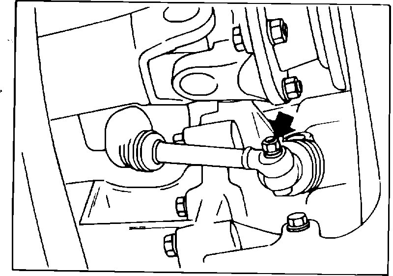
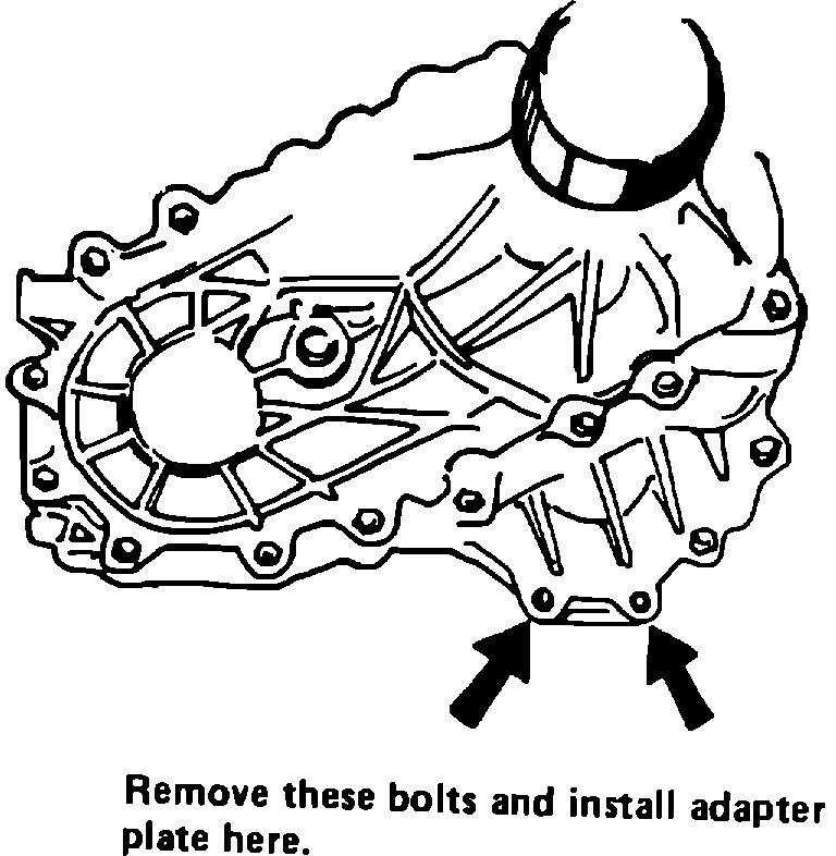
FIGURE 14
31. Remove the two lower bolts at the rear of the transfer case (Figure 14).
FIGURE 15
32. Mount the transmission/transfer case jack adaptor (Special Tool # GP8600) to a transmission jack using shop bolts.
33. Raise the transmission jack and mount the jack adaptor to the transmission/transfer case (two bolts at cross member mount and two bolts at rear of transfer case) (Figure 15).
FIGURE 16
34. Remove the tall jack stand under the tail shaft.
35. Remove the four front mounted bell housing bolts (14 mm) (Figure 16).
36. Support the engine with a jack stand under the oil pan. Use a block of wood as a spacer between jack and oil pan.
37. Remove the remaining five bell housing bolts.
38. Move the transmission/transfer case rearward and lower from vehicle.
WARNING: Transmission/transfer case assembly weighs approximately 300 lbs. Use extreme caution when handling.
FIGURE 17
39. Remove the transfer case from the transmission (thirteen 14 mm bolts) (Figure 17).
__________________________________________
Let me know your thoughts. The only thing that has me questioning broken parts is there is no noise.
Let me know.
Joe
Images (Click to make bigger)
Monday, December 21st, 2020 AT 8:36 PM
