Further testing info for the TCC, it's a common part failure and the solenoid is almost always the problem, here's some testing you can do.
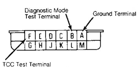
CHECKING VOLTAGE TO TERMINAL "A" AT TRANSMISSION USING ALDL Connect one end of test light to terminal "A" at ALDL. See Fig. 2 . Connect other end to terminal "F" at ALDL. Turn ignition on. Test light should light. Some transmissions must be in 3rd gear before test light will light. If test light does not light, see CHECKING VOLTAGE TO TERMINAL "A" AT TRANSMISSION. If test light lights, 12 volts are present at terminal "A" at transmission. See CHECKING FOR GROUND AT TERMINAL "D" AT TRANSMISSION USING ALDL. CHECKING VOLTAGE TO TERMINAL "A" AT TRANSMISSION 1. Check for 12 volts to terminal "A" at transmission. See WIRING DIAGRAMS . Raise and support vehicle. Ground test light. Unplug connector at transmission case and install tip of test light into terminal "A". DO NOT depress brake pedal. On computer-controlled vehicles, turn ignition on. Test light should light. 2. On all other vehicles, start engine and run to normal operating temperature. Raise engine speed to 1500 RPM. Test light should light. If test light lights, see CHECKING FOR GROUND AT TERMINAL "D" AT TRANSMISSION. If test light does not light, ensure fuse marked "gauges" is okay (most models). CHECKING FOR GROUND AT TERMINAL "D" AT TRANS. USING ALDL 1. Before performing this test, CHECKING VOLTAGE TO TERMINAL "A" OF TRANSMISSION USING ALDL test must pass. Otherwise, see CHECKING FOR GROUND AT TERMINAL "D" AT TRANSMISSION. Test light should be connected between terminals "A" and "F" at ALDL connector. See Fig. 2 With engine at normal operating temperature, road test vehicle. When road test is started, test light should light. 2. If brake pedal is applied, test light will not light. Watch test light to see if test light goes out during road test. If test light goes out, terminal "D" is grounded at transmission. See GROUNDING "D" WIRE AT TRANSMISSION USING ALDL . If test light does not go out, a computer system problem exists. See CHECKING SELF-DIAGNOSTIC SYSTEM. CHECKING FOR GROUND AT TERMINAL "D" AT TRANSMISSION 1. Check for ground at terminal "D" at transmission. See WIRING DIAGRAMS . On non- computer controlled vehicles, see COOLER LINE PRESSURE TEST. On all other vehicles, raise and support vehicle (if necessary). Disconnect transmission electrical connector and connect test light ground wire to terminal "A" of transmission connector. Install tip of test light into terminal "D" of transmission connector. 2. Start engine and run to normal operating temperature. Place gear selector in Drive (O.D. on 4 speed transmissions). Accelerate slowly to 60 MPH. Test light should light. If test light does not light, computer system problem exists. Shave insulation off of wire "D", or pierce wire near transmission connector. 3. Connect one end of jumper wire to wire "D" at shaved or pierced area. Ground other end of jumper wire. With vehicle on lift, road test for lock-up. If unsure lock-up occurred, hold steady speed of 60 MPH and slightly touch and release brake pedal. Disengagement and re- engagement should be felt. Seal bare wire connection with silicon after test is complete (if necessary).
Follow this to adjust both the brake switch at the pedal and the neutral saftey switch.
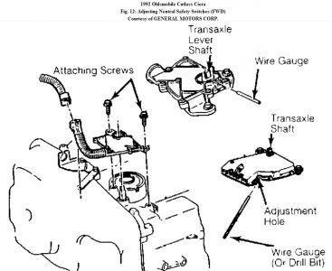
FWD Models 1. There are 2 different neutral safety switches used on FWD models. See Fig. 12 . To adjust switch, place gear selector lever in the "N" position. 2. Ensure shift cable is adjusted correctly and transaxle lever is in Neutral position. Loosen switch attaching screws. Rotate switch on shifter assembly to align adjustment hole with carrier tang hole. 3. Insert a 3/32" (2.4 mm) wire gauge about 5/8" into switch holes. Tighten attaching screws. Remove wire gauge. New switches may have plastic pin installed in hole. Plastic pin is designed to shear off during shift lever operation. Fig. 12: Adjusting Neutral Safety Switches (FWD) Courtesy of GENERAL MOTORS CORP. TORQUE CONVERTER CLUTCH BRAKE SWITCH The torque converter clutch brake switch must be adjusted to prevent vehicle stalling at idle due to the clutch remaining applied. Ensure brake pedal is fully released. Adjust plunger to just touch brake pedal lever. Page 1 of 1 5/27/2010 ...
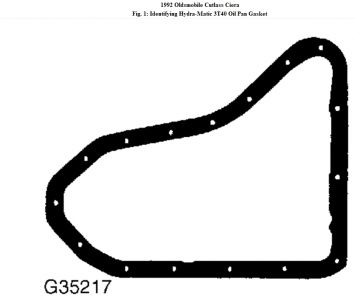
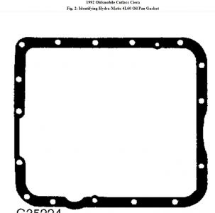
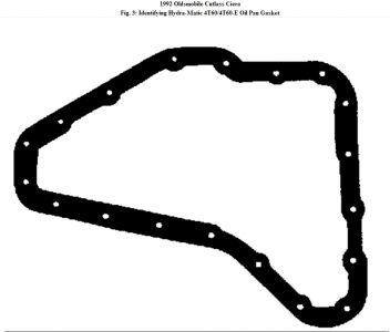
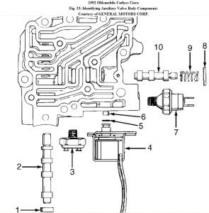
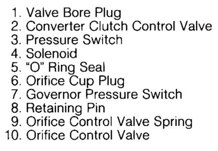
Which Gasket matches yours? and here is the ALDL id.
SPONSORED LINKS
Saturday, September 26th, 2020 AT 10:31 AM
(Merged)


