Replace or at least test the ignition switch, not the key, but the platic part that plugs into the harness, it's on the same fuse as the starter relay. Here's how.
STEERING COLUMN SWITCHES -2000 Ford Taurus SE
Page 1 of 1

STEERING COLUMN SWITCHES -2000 Ford Taurus SE
Page 1 of 1
TEST C: IGNITION SWITCH INOPERATIVE
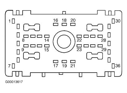
1.Remove and inspect fuse F107 (40-amp) from battery junction box. If fuse is blown, replace fuse. If fuse blows again, go to next step. If fuse is okay, go to step 4 . 2.Turn ignition switch to OFF position. Disconnect ignition switch connector C250. Measure resistance between ground and output side of fuse F107 (40-amp). If resistance is greater than 10 k/ohms, go to next step. If resistance is less than 10 k/ohm , repair short to ground in appropriate wire. See POWER DISTRIBUTION article in WIRING DIAGRAMS. 3.Install fuse F107 (40-amp). Ensure ignition switch connector C250 is disconnected. Measure voltage at terminals B1, B3, B4 and B5 (all Light Green/Violet wires) at ignition switch connector C250. If voltage exists at all terminals, go to next step. If voltage does not exist at any terminals, repair open in Light Green/Violet wire. 4.Test ignition switch. See IGNITION SWITCH under COMPONENT TESTS. If ignition switch is okay, go to next step. If ignition switch is defective, replace ignition switch. See IGNITION SWITCH under REMOVAL & INSTALLATION. 5.Turn ignition switch to OFF position. Connect ignition switch connector C250. Disconnect central junction box connector C270b. Turn ignition switch to RUN position. Measure voltage between ground and terminal No. 20 (Gray/Yellow wire) at central junction box connector C270b. Measure voltage between ground and terminal No. 21 (Red/Light Green wire) at central junction box connector C270b. Measure voltage between ground and terminal No. 33 (Red/Light Blue wire) at central junction box connector C270b. Measure voltage between ground and terminal No. 17 (Black/Light Green wire) at central junction box connector C270b. See Fig. 3 . If voltage exists at all terminals, replace central junction box. If voltage does not exists at any terminal, repair open in appropriate wire(s). See POWER DISTRIBUTION article in WIRING DIAGRAMS. Retest system operation.
Fig. 3: Identifying Central Junction Box Connector C270b Terminals
Courtesy of FORD MOTOR CO.
10/18/2008
Sunday, April 26th, 2020 AT 12:44 PM
(Merged)


