No crank, no start has a brand new battery ?

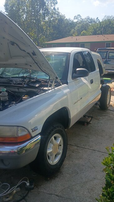
1997 DODGE DAKOTA
165,000 MILES • 5.2L • AUTOMATIC
Avatar
DALEC6328
  • MEMBER
  • 65 POSTS
I have a 1997 Dodge Dakota SLT 5.2 that has a brand new battery a brand new starter a brand new crankshaft positioning sensor a brand new fuel pump brand new ignition switch and I still cannot get it to crank it will spin the starter if I if I jump the trigger wire but it won't fire, it will also actually crank if you Palmer the fuel body I mean the throttle body and jump to starter trigger it will actually crank and run so I don't know. Other than that it won't crank.it won't Even turn the starter over I've checked all relays and fuses, I've done the 30 minute capacitor reset, I've done the 10 minute key reconfiguration, I've grounded the remote on the window to try to bypass the ats. any ideas
Aug 16, 2026 at 2:21 PM
Advertisement
Avatar
CARADIODOC
  • Experienced Mechanic
  • 34,366 POSTS
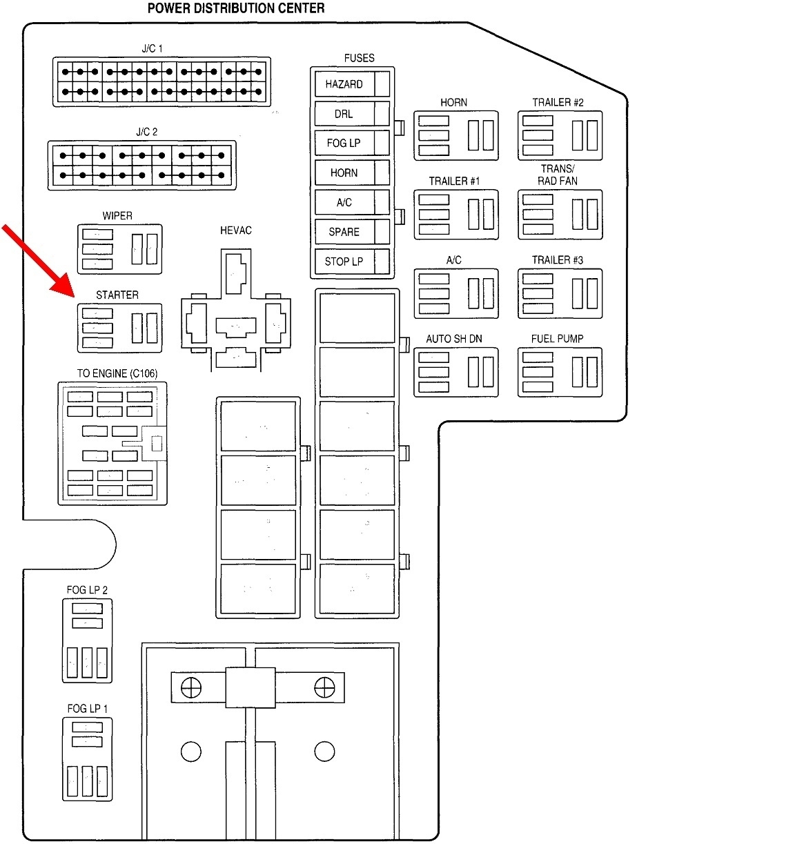
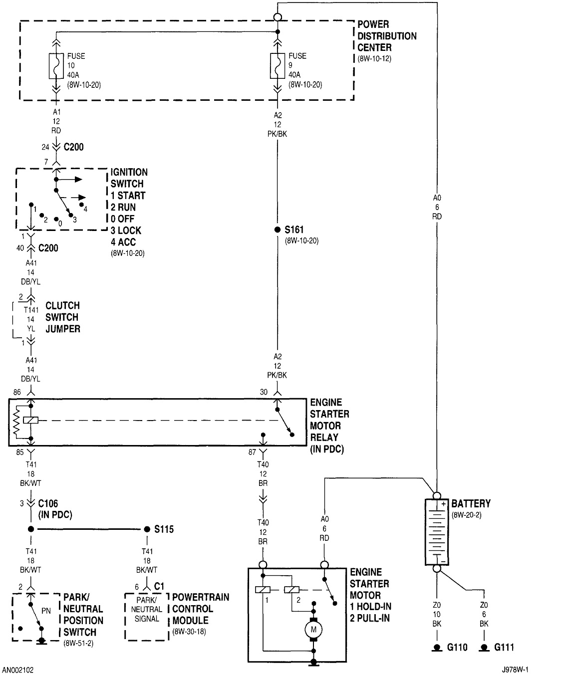
Sounds like you did all the complicated and uncommon stuff. Now we need to focus on the simpler things. The cranking system can be broken down into four separate circuits, each with a test point at the starter relay.

Remove the starter relay, then use a test light for these tests. Be careful to just touch the test light's probe to the terminals. If you stuff the probe into a terminal, that will stretch the terminal and cause a bad or intermittent connection later.

Where you see three terminals parallel to each other in the relay socket, disregard the middle one. Of the other four, one must have 12 volts all the time. Without looking, I think that will be one of the two on the right in the drawing. Next, you'll need a helper for this. Of the remaining three terminals, one must have 12 volts when the ignition switch is in the "crank" position.

If you have both of those 12-volt feeds, move your test light's clip lead to the battery's positive post. We'll be checking for grounds next. Of the two remaining terminals, the test light should light up on both of them.

One of those four tests has to fail, unless the relay is defective. If you're missing the constant 12 volts, check the 40-amp fuse. If you're missing the switched 12 volts, the ignition switch is the best suspect. There were three different switch designs. One used a round cam on the end of the ignition cylinder. Those were known for breaking, then the switch wouldn't go quite far enough to hit the "crank" contact. The dealer's parts department has a repair kit for that. Your truck should be new enough that is uses an updated design. Those didn't cause many problems.

For the ground circuits, one is the feed to the starter solenoid. The best suspect there would probably be a rusted terminal at the starter. The better suspect is the last one. That's the ground for the relay, and it goes to ground through the neutral safety switch. If that circuit is okay, you can identify it by observing the ground path goes away, (test light turns off), when your helper shifts out of "park" or "neutral".

Let me know which of those tests fails. I'll be back tomorrow to figure out where to go next.
Aug 16, 2026 at 6:07 PM
Avatar
DALEC6328
  • MEMBER
  • 65 POSTS
Ok. Thanks for replying so fast. I have used a multimeter on the relay and have 2 at 12 when on. I'll do the other tests in the morning and let you know. I really don't know what I'm doing but I got this truck for my son and I really want to get it running. Lol
Aug 16, 2026 at 7:02 PM
Avatar
DALEC6328
  • MEMBER
  • 65 POSTS
Okay so I just did the test that you told me about and the results from what I found the phone the test light and the voltmeter on the starter relay is that the ground is actually in the middle of this one call me a lights up on the test light for Brown in the middle pin not the middle on the back but the middle on the front of the two sideways ones then you got the three lined up or it's the one right below the three that are lined up this lighting up or whenever the test light is connected to the positive battery terminal that's the one that lights up
Aug 17, 2026 at 6:51 AM
Avatar
DALEC6328
  • MEMBER
  • 65 POSTS
I don't know if the neutral safety switch is good or not. I tried to test it but I'm not sure if I'm doing it right. It completely threw me off that test light lighting up on that middle pin on that relay for it to be ground. Idk what to do now
Aug 17, 2026 at 6:58 AM
Avatar
DALEC6328
  • MEMBER
  • 65 POSTS
I must also tell you that as you can tell I have absolutely no idea what I'm doing but I've dozen the middle of this truck it started off when we bought it as it had a no spark issue which it turned out when I looked into it I mean but we can put in a battery and crank it turn it over at primer the throttle body and it would crank up but then put it on tow truck and brought it to the house and we put a battery or put a battery in it and I don't guess it was strong enough to crank it up I found out that it had a rats had gnawed through the crankshaft position sensor plug so I replaced that. And same problem once I replace the crankshaft position sensor we didn't have a battery strong enough to turn it over but I could I can get it running with cranking it or the jump start and primer in the throttle body and we replace the fuel pump then we replace the the starter dimmer replaced the ignition switch and yeah I don't know I mean I've I've done I've done that capacitor resistance reset thing on the PCM and I don't know it I've screwed up things are not all the wires are still the same I haven't spliced into anything I haven't switched around anything or anything like that so I don't know
Aug 17, 2026 at 7:03 AM
Avatar
CARADIODOC
  • Experienced Mechanic
  • 34,366 POSTS
There is no "capacitor reset". That terminology refers to allowing storage capacitors to discharge for two minutes after disconnecting the battery when you want to work in the air bag system. When we're charging customers by the hour, we don't even waste their time by doing that. Air bag systems are so well protected and designed to not deploy accidentally. That's why you never hear of someone getting hurt by them.

All of the other things you originally mentioned have nothing to do with the starting system. Here's a totally different way to approach this. All starter systems can be broken down into three circuits; the low-current circuit that includes the ignition switch, half of the relay, and the neutral safety switch, the medium-current circuit that includes the other half of the relay and the starter solenoid, and the high-current circuit that includes the starter motor and the two fatter battery cables.

A real easy and fast way to test the low-current circuit is to put your finger on the starter relay, then have a helper turn the ignition switch to "crank". If that circuit is working, you'll feel the relay click. There can be some confusion if you aren't paying close attention as other relays also turn on and off. In particular, the automatic shutdown, (ASD) relay turns on for one second, then turns back off when the ignition switch is turned on, (turned to "run", not to "crank"). Just turn the ignition switch to "run", wait a couple of seconds, then turn it to "crank". At that point only the starter relay should click.

If you feel the starter relay click, we're done in that circuit. The ignition switch and neutral safety switch are okay.

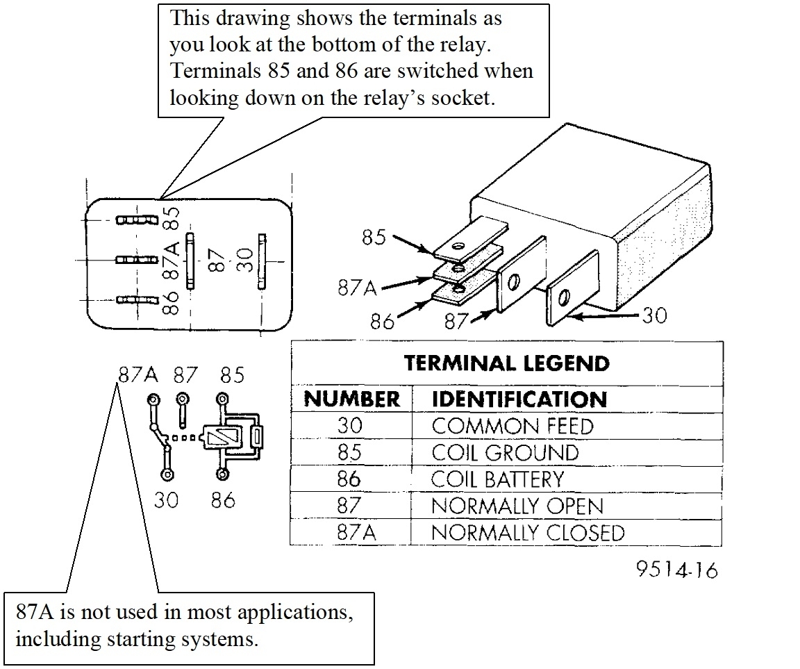
Next, remove the starter relay, then use a piece of wire to jump terminals 30 and 87 together in the socket. I found this drawing to show the terminal layout. 30 and 87 are the two larger terminals that are parallel to each other. I use a stretched-out paper clip for this, but this circuit can easily draw ten amps, so be aware that paper clip can get hot pretty quickly. This will make the starter solenoid kick in with a rather loud clunk. We usually don't hear that over the noise of the starter cranking the engine, but if you only hear that clunk and the starter doesn't spin, there's a common cause for that with a rather inexpensive fix. We can discuss that further if it becomes necessary. By the way, if you hear that loud single clunk in the first test, we can move right to the high-current circuit.

When that solenoid kicks in, it pushes the drive gear into mesh with the ring gear on the transmission. Once fully engaged, a very large contact disc turns on the high-current circuit to run the starter motor. Those contacts are a common source of trouble, but we also have to consider the battery cables. Most commonly when a cable causes a problem, the strands of wire are corroded away under the insulation where you can't see it. I have other tests we can do next to narrow down the source of the trouble in that circuit.

See how far you get with these tests and observations, then let me know what you find.
Aug 17, 2026 at 2:11 PM
Avatar
CARADIODOC
  • Experienced Mechanic
  • 34,366 POSTS
I got so wrapped up in my reply that I completely overlooked your dandy video. You had the clip lead on the positive post correctly for the last two measurements. On the first terminal you touched, terminal 30, you have 12 volts there, AND on the clip lead. The difference between them is 0 volts, so the test light did not light up. That is correct.

Next, when you touched the probe to terminal 87, that medium-current circuit goes to ground through the two coils that make up the starter solenoid, (built into the starter motor). The resistance of those two coils is so low that to the test light, it looks like a good circuit to ground. The clip lead is still on the battery's positive post, so now the difference is 12 volts and the test light lights up. That medium-current circuit is good.

Your last two tests on terminals 85 and 86 went by kind of fast, but I didn't see the test light turn on for either of those. It should have lit up on the top left terminal, number 85, if the transmission was in "park" or "neutral".

Double-check that last test very closely. Clip lead on battery's positive post. Lightly touch the probe to the top left terminal. If it doesn't light up, ask a helper to shift between "park" and "neutral" a few times. If the test light flickers or only lights up in "neutral", the neutral safety switch is the best suspect.

The back-up light switch is built into the neutral safety switch. Turn the ignition switch to "run", then shift to reverse and see if the back-up lights turn on. If they do not, suspect that switch connector is unplugged. Those two switches have nothing electrical in common other than they're both built into one small assembly. You'll have to crawl under the truck to check that. The switch is on the driver's side of the transmission, just a few inches above the pan, kind of close, as I recall, to the middle or back corner of the pan. It's a round plug with three wires.

If you do find that connector is unplugged, there's two ways it can be plugged in. All three terminals are in a straight line. The two on the ends are for the back-up lights. The middle one is for the starter relay.

If the test light still never turns on at terminal 85, the neutral safetty switch is the likely suspect, but we can do a couple more tests to be sure, if you want to. Let me know what you find.
Aug 17, 2026 at 2:38 PM
Avatar
DALEC6328
  • MEMBER
  • 65 POSTS
Ok so I redid that one several times and the light never came on. I'm under it now and there's a few disconnected plugs.
Aug 17, 2026 at 3:51 PM
Avatar
DALEC6328
  • MEMBER
  • 65 POSTS
Also the brake lights didn't work
Aug 17, 2026 at 5:50 PM
Avatar
DALEC6328
  • MEMBER
  • 65 POSTS
The relay clicked
Aug 17, 2026 at 6:23 PM
Avatar
DALEC6328
  • MEMBER
  • 65 POSTS
When I did the jumper wire the starter actually spun
Aug 17, 2026 at 6:30 PM
Avatar
DALEC6328
  • MEMBER
  • 65 POSTS
I forgot to put it in neutral etc on that test light part for the safety switch.
Aug 18, 2026 at 7:29 AM
Avatar
DALEC6328
  • MEMBER
  • 65 POSTS
I just looked at your stats! Wow man!!! Nice work
Aug 18, 2026 at 2:14 PM
Avatar
CARADIODOC
  • Experienced Mechanic
  • 34,366 POSTS
I'm a little confused. If you jumped terminals 30 and 87 together and the starter cranked the engine, that proves the medium-current and high-current circuits are okay. If you felt the starter relay click when a helper turned the ignition switch to "crank", that low-current circuit is okay too. That just leaves the relay itself. The only part of it that wasn't included in any of these tests is the switching contacts. Those can burn away or corrode away. While neither is very common, it is time to try a different relay.

Switch the starter relay with one of the other ones like it. The wiper or horn relays are good choices. Don't use the fuel pump or automatic shutdown, (ASD) relays as either of those will prevent the engine from running.

Let me know if that solves the problem. If it does not, we'll have to restart the testing with more clarity or attention to detail.
Aug 18, 2026 at 7:28 PM
Avatar
DALEC6328
  • MEMBER
  • 65 POSTS
I've already done that before. Let me ask you this. All those relays appear to be exactly the same. Are they? Is there a difference and how can I tell because I got into the relays one day drunk and on my meds and started moving them all around testing them in different ports
Aug 18, 2026 at 7:43 PM
Avatar
DALEC6328
  • MEMBER
  • 65 POSTS
Oh yeah when I did it before I put each relay into the horn relay to see if the relay worked. They all honked... That's what I was told to do... Idk if that's correct
Aug 18, 2026 at 7:44 PM
Avatar
CARADIODOC
  • Experienced Mechanic
  • 34,366 POSTS
Okay, somewhere we overlooked some detail or I misinterpreted something. Start by feeling for the starter relay's click again. If you don't feel it, look at the female terminals in the socket to see if they got stretched by the test light probe.

If the relay does click, go down to the starter and test for 12 volts on the smaller wire next to the large battery cable. 12 volts should appear there when your helper turns the ignition switch to "crank". Test lights with regular incandescent bulbs don't have a polarity, so this test can be easier if you can connect its clip lead to the smaller terminal down on the starter solenoid, and ground the probe somewhere where it's easier to hang onto, such as right on the battery's negative post. Of course, you can ground the clip lead to the battery's post and hold the probe down on the solenoid too, if you don't mind laying on the ground for that test. Either way will give the same result.

Yes, all of these relays are the same. Burned contacts may not show up with some tests. You need to draw substantial current to make bad contacts show up. Running them in the horn circuit does that. A pair of horns will draw a good ten amps or more. That's similar to how much current is drawn by the starter solenoid. If a relay works for the horns, it will be okay in other circuits too.
Aug 18, 2026 at 8:12 PM
Avatar
DALEC6328
  • MEMBER
  • 65 POSTS
I've done jacked it up and put it on stands for now. I was checking out first to see if I was pressurized(which I was) so we did some multimeter readings on the wiring harness and those readings I didn't really understand the results. I did all this because it's a new fuel pump and I haven't heard it come on once. But I did jump 30 to 87 on it before too when I primered the throttle body and jumped the starter relay pins while I had the fuel pump jumped just to see if It would stay running from the primer by forcing the fuel pump to keep running. No luck. I also have the PCM pin out diagram and I have marked the sensor signal pins and the power pins both 12 and 5 volts. As well as the p/n switch signal, and a few other pins that I thought you might be able to sift thru and notice something off. This began with research into the asd and how this guy on YouTube demonstrated how to test them out at the PCM. You see, I don't have a job per say, so I have all day long to ponder and just look at the truck and I'm impatient as can be so I'm just researching asd, PCM repair, and how to just redneck engineer it to crank and run to maybe backtrack the stuff. But now that I have somebody competent and willing to teach me some things, I'm much more relaxed knowing that you know what you're talking about and are helping me out. Thank you again.
Aug 19, 2026 at 5:59 AM
Avatar
DALEC6328
  • MEMBER
  • 65 POSTS
Ok so my developments for today have been as follows. I did PCM pin out multimeter test on some and have the results written down. Just crawled under and straightwired the p/n safety ground pin to the chassis and BOOYAKA. CRANK BUT NO FUEL SUPPLY so I don't know how to fix it so that it cranks with the ignition switch and then comes the fuel system I guess if you don't mind
Aug 19, 2026 at 1:47 PM
Avatar
DALEC6328
  • MEMBER
  • 65 POSTS
Oh yeah the relay wasn't clicking, it felt more like a pull kinda, so I tightened the female tabs and then it clicked
Aug 19, 2026 at 1:49 PM
Avatar
CARADIODOC
  • Experienced Mechanic
  • 34,366 POSTS
Okay, we're making progress. This is being complicated by not knowing what the previous owner messed up.

First let me explain how the ASD relay works and what it does. That will prevent you from wasting time in the sensor circuits.

The term "automatic shutdown" by itself is confusing. They should have called it the "run" relay. This goes all the way back to the mid 1980s models. That relay is turned on by the Engine Computer, (Powertrain Control Module, or "PCM"). Normally it gets turned on two times. The first time is for just one second when you turn on the ignition switch. (You might hear the hum of the fuel pump for that one second). Next, the computer turns it on again when it sees engine rotation, (cranking or running). It knows that by the signal pulses it receives from the crankshaft position sensor and the camshaft position sensor. On models from somewhere around the early 2000s all the way back, both signals are required for the computer to turn the ASD relay on. In later models, the engine would continue to run if one sensor failed, but once stopped, the engine would not restart on just the one signal. I'm told in still later years the engine would start and run on just one working sensor in a back-up mode.

When you look at a new camshaft or crankshaft position sensor, if you see it has an oval-shaped bolt hole for mounting it, or a "U"-shaped slot, that design is adjustable for how far it is stuffed into the engine. That air gap is critical. To set that gap, new sensors come with a thick paper spacer glued to the end, or a thin plastic rib is molded onto the end of it. The paper spacer will slide off and be lost the first time the engine is cranked. The thin plastic rib can wear down a little. If you remove, then reuse one of these sensors, you can get a new paper spacer from the dealer's parts department. They only cost about a quarter, but I used to cut them in half to get two repairs out of one part. That saved one customer 25 cents! If you reinstall a sensor with the plastic rib, you're supposed to cut off the remaining part of the rib, then use one of those paper spacers. One mistake to be aware of here is if that paper spacer is required but not used, it is possible to push the sensor in too far where it can be hit by the teeth on the ring gear on the transmission. That will break the sensor.

If one or both of your sensors have a round mounting hole or the mounting ear hangs off to the side, those have the depth set automatically and there is no adjustment and no need for a paper spacer.

When the ASD relay gets turned on, it sends current to a number of places including the ignition coil(s), injectors, oxygen sensor heaters, alternator field, and fuel pump or pump relay, depending on model and year. If your truck uses a separate fuel pump relay, you can bypass it to listen for the hum of the pump by again, jumping terminals 30 and 87 in its socket. It sounds like that's what you did. Even though the fuel pump is running, you still need the ASD relay to turn on so you can power up the injectors and ignition coils. Then, even if you jump the ASD relay too, you still need the signal pulses from the crankshaft and camshaft position sensors for the computer to know when to fire each injector and coil. The bottom line is if one of those sensor signals is missing, you can jump a relay to allow testing in that circuit without having to crank the engine, but the engine isn't going to run.

Everything depends on those two sensor signals, so that's what we have to concentrate on once the cranking issue is solved. There's two ways to approach this. The less-desirable way is by reading the diagnostic fault codes in the Engine Computer. One problem here is for those sensors, it can take quite a bit of time for the computer to recognize one is missing and to set a fault code for it. Any codes that were in the computer got erased when the battery was disconnected / replaced. Any codes for intermittent defects not currently occurring also get self-erased after 50 engine starts. Next, simply cranking the engine may not be enough time to set a fault code for these sensors. It often takes coasting to a stop with a stalled engine for the missing signal to be detected. For this reason, never assume those sensors are okay just because there's no fault code set for them.

The better way to check for these signals is to use a scanner to view "live data" and see what the computer is seeing and responding to. I have a Chrysler DRB3, (diagnostic readout box, version 3), for all of my older vehicles. Those went obsolete beginning with the 2004 Dakota / Durango, and on all Jeep models by 2008, as I recall. Depending on the year this scanner was built, they will work on models back to 1996 or 1998. With an extra, plug-in card, (in a slot on the bottom), it will work on models back to 1994 with the "Supercard 2" or on models back to 1983 with the "Supercard 1). The Supercard 2 also allows it to do emissions-related testing on any car brand sold in the U.S. starting with 1996 models. For that reason, a lot of independent repair shops bought them. Since they're obsolete now and there are much better alternatives, you can find these on eBay, but they still bring big bucks. When these were new, they were available from the manufacturer on their web site for $6200.00 for a rather extensive kit, but that didn't include any of the extra cards that were available. The last time I looked, they were going for around $2000.00 on eBay.

A better value is the Snapon Solus Edge. I got mine on eBay for my newer vehicles. The problem with these is the annual updates are extremely expensive, so a lot of shops just keep one updated and let their others become outdated, then they buy a new one. At roughly $4000.00 that's cheaper than spending $1000.00 per year for four years and ending up with an up-to-date four-year-old scanner. You also have to pay extra for Asian import coverage and more again for European import coverage. One of those includes Harley Davidson. I bought my used Solus Edge from a reseller on eBay in 2018 updated to that time, and I've never updated it beyond that. My two newest vehicles are 2014 models, a I plan to never buy anything newer.

A still better value to consider is a scanner from Autel. One of our other experts recommended it so I looked into it and bought one, also on eBay. For $1300.00 I can program keys and modules, and I have full coverage for every car brand in the world. That's right, I can diagnose a Russian car if they can drive it over to me!

Getting back to the DRB3 and the cam and crank sensors, on the live data screen, you scroll down to the sensors and both will be listed with a "No" or "Present". Both will show "No' at first, then you want to see them switch to "Present" as soon as you start cranking the engine. If one of them stays on "No", that is the circuit that needs to be diagnosed, regardless if a fault code for it is set or not. The aftermarket scanners display the same information, but I don't remember the exact wording.

A scanner is a good value if you're going to have more use for it, and if you've never used one, you're in for some fun as there's so much you can see and a real lot of stuff you can command computers to do, such as turn relays on and off. The least expensive route is to get a simple code reader. Those go for around $30.00 to maybe $80.00. The biggest problem with these is while almost all of them now also display sensor data, the screens take a painfully long time to update, as in two to three seconds. That's way more than enough time to miss little glitches when you're manipulating, say, a throttle position sensor, and watching for a dropout. You'll never see that dropout unless it lasts long enough.
Most scanners have a recording capability where you can replay a few seconds of data very slowly to watch for any elusive glitches.

All of this scanner information is pointless if all you want to do is read fault codes, and only in the Engine Computer. Chrysler made doing that yourself much easier than any other manufacturer. Simply turn the ignition switch from "off" to "run" three times within five seconds without cranking the engine. Leave it in "run" then watch the code numbers appear in the odometer display. (On 1995 and older models you count the flashes of the Check Engine light to read the codes). Either way, you can go here:

https://2carpros.com/trouble_codes/obd2/

to see the definitions, or I can interpret them for you. By the way, 1996 is when they started with the OBD2 emissions system, (on-board diagnostics, version 2), which included the three-digit fault codes. That was a standardized computer language used on all vehicles sold in the U.S. starting with '96 models. For 1995 and older models, every manufacturer had their own computer systems with nothing interchanging. You have to watch that any aftermarket scanner is capable of talking to the computers on your vehicle. On the page I just listed with the fault code definitions, way at the top it lets you "switch to OBD1 codes" if you're diagnosing a '95 or older model. Each brand is listed separately and each one includes instructions on how to get the codes. Chrysler is the easiest, by far. Ford is one of the most complicated and miserable.

When it comes to the crankshaft and camshaft position sensors, there's two basic designs. Older vehicles typically used two-wire sensors. Those were nothing more than a long, thin wire wrapped around a magnet. On some cars, accidentally switching those two wires had no effect on engine operation. On some, it changed slightly when an ignition coil or injector fired. Later models almost always use three-wire sensors. Those have the same coil of wire around a magnet, but to be more precise in their timing, they generate rather weak signals. Therefore, they build in an amplifier circuit that needs a ground and a power supply of 5, 8, 10, or 12 volts. Chrysler usually uses a very carefully regulated 5.0 volt supply. None of these wires can be switched, so if a previous owner was in there doing some wiring, that's a good place to start. If you see splices or other evidence of someone being in there, I can find the connector diagrams and post them for you. Those include the wire colors for each terminal.

All of this wondrous information applies after we get the starting system working. At this point, don't waste your time testing other sensors. We'll revisit the cam and crank sensors if necessary, and all but one of the other sensors won't prevent the engine from running. If you have a defective coolant temperature sensor, for example, or throttle position sensor, or intake air temperature sensor, the engine will run with those failures, then the Engine Computer will detect those defects and set a fault code to let us know where to start the diagnosis. It's also important to be aware that fault codes never, ever say to replace a sensor. When a sensor or other parts is referenced in a fault code, it is actually the cause of that code only about half of the time. First, we have to rule out wiring and connector terminal problems, and mechanical problems associated with that part. This is why we read way too often that someone "replaced a sensor three times and the same code still sets". It isn't a bad sensor. It's usually one of the wires going to it.

By the way, once we have the starting system working properly, I'll have you start a new question for the cam and crank sensors or any other, unrelated problems. That's done for the cataloging process. With multiple topics covered in one question, someone researching a similar problem will never see our newer conversation as it won't show up on any list. Also, this has become a private conversation between the two of us. As such, none of the other experts are likely to see the new topic or have a chance to reply. Believe it or not, sometimes I'm not the best person to continue with the new topic. My specialties are electrical, suspension and alignment, and brakes. Outside of those areas, I usually defer to people smarter than me!

So if I read this right, you have the starter working now, but you had to bypass the neutral safety switch? If I have that right, that switch is suspect. Failures are not so common that I wouldn't trust a used one from a salvage yard, but be aware there is an aluminum gasket on them that should be replaced too. If you get a new switch from the dealer, they will have that gasket too. Don't try to seal the switch with Teflon tape as that will insulate the ground circuit for the starter part of the switch, then you'll have the same problem.

Let me know when you're ready for a pat on the back.
Aug 19, 2026 at 4:27 PM
Avatar
DALEC6328
  • MEMBER
  • 65 POSTS
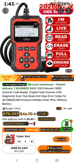
This is the OBD2 scanner that I have
Aug 19, 2026 at 10:49 PM
Avatar
DALEC6328
  • MEMBER
  • 65 POSTS
But I don't have a clue what any of it means
Aug 19, 2026 at 10:49 PM
Avatar
CARADIODOC
  • Experienced Mechanic
  • 34,366 POSTS
This looks like a fairly respectable unit. It will not read codes or data on any 1995 or older vehicle. Those were OBD1, (on-board diagnostics, version 1), emissions systems with two-digit fault codes that didn't get terribly specific. Every manufacturer had their own proprietary computer language. As such, code readers and scanners for those vehicles will list the brands they work on. The first aftermarket scanner I bought for myself had one cartridge to do Chrysler, GM, and Ford models, but no others. At that time, (early 1990s), it was rare to find any scanner that could do more than one brand.

Your reader will talk to OBD2 vehicles. Every brand sold in the U.S. starting with '96 models had to use that standardized computer language. It included three-digit fault codes that can get pretty specific. There can be roughly two dozen codes that just pertain to the oxygen sensors, for example.

EOBD stands for "enhanced on-board diagnostics". I see that quite often, but I'm not sure what the difference is. I seem to recall that might have something to do with Ford models. Regardless, your reader will use the correct computer language automatically.

OBD2 systems began being phased out on Chrysler models in the early 2000s. 2003 was the last year for Dakotas and Durangos. 2008 was the last year for some Jeep models. It was replaced by the "CAN" system. That is "controller area network". You may also see "CAN Buss". That refers to a data buss which is a pair of wires connecting all the dozens of computers to each other for them to talk back and forth. There are data busses on your truck too, but newer models can have up to four of them. The low-speed buss is used for items of low importance such as power door locks and power windows. The highest speed buss is used for things where timing is critical, mainly air bags and anti-lock brakes. The Engine Computer commonly uses two of the busses.

On a data buss, each computer gets a turn to transmit its data to all the other computers. Those other computers use what they need and simply disregard the unneeded information. This saves miles of wire. A good example would be the Engine Computer has to know coolant temperature to know when to go to "closed loop", meaning it includes the oxygen sensor readings in its fuel metering calculations. The Transmission Computer wants to know coolant temperature to adjust shift schedules. They want to delay upshifts when the transmission fluid is still cold and flows sluggishly through the cooler. The instrument cluster needs to know coolant temperature to know where to place the pointer for the temperature gauge. That means you need three coolant temperature sensors along with all their wiring. Instead, there's just one and it's connected to the Engine Computer. When the Engine Computer broadcasts its data onto a data buss, the Transmission Computer and instrument cluster see that, but they will disregard other unneeded parts of that message. The Body Computer is watching this data too, but in this sad example, coolant temperature has no effect on it running the power windows or power seats, so it disregards the information.

With the CAN Buss system, instead of just having two to three dozen computers, now almost everything is turned into a small microcomputer. That includes the headlight switch, headlamp and tail lamp assemblies, radio, heater control panel, etc. Most of us feel that adds a lot of unnecessary complexity to the electrical system, along with a lot more problems, but the engineers will argue you can get a lot more diagnostic information that should make diagnosis easier. Today we have well over 2,000 potential fault codes just from the Engine Computer. Add to that other fault codes can be stored in the Transmission Computer, Air Bag, Anti-Lock Brake, Body, HVAC, Speed-Sensitive Steering Computers, and even in the front fuse box on a few models. A 1980s "K-car", Plymouth Reliant / Dodge Aries had more computer power than the moon lander had in 1969, and the newer car models have gone way beyond that by a thousand times.

I don't know what they're referring to about, "without battery". Scanners have internal batteries built in, but most also run on a 12-volt feed wire in the diagnostic connector. That saves the internal battery, and many scanners will charge their internal battery while it's connected to the vehicle. Code readers typically do not have their own batteries. They power up automatically as soon as they're connected to the diagnostic connector.

A typical application of needing the battery in the scanners has to do with updating software in a computer. In the 1980s, if a model was involved in an emissions-related recall that required a change to its software, we had to replace that computer. The old one got sent back, updated, then it got a new sticker with a new part number. That was very expensive for the manufacturer.

Beginning by around the mid to late '90s, the software could be updated in many computers at the dealership. We connected Chrysler's DRB3 to a giant standalone computer that talked directly to Chrysler over a satellite feed, and downloaded the software update into the scanner. Next, the scanner got unplugged, then connected to the customer's car to transfer that update into their computer. The scanner's internal battery allowed us to do that. Also, it was not unheard of to install that update into a half dozen new cars still sitting on the sales lot. All of those updates could be performed in a matter of minutes without having to replace any computers.

"I/M readiness" is one of my weakest areas, but I can share as much as I know. In the past, when you lived in an area that required periodic emissions testing, they had to stick a probe up the tail pipe, take time-consuming measurements, and analyze the data before the car would pass. Readiness monitors do that for you, . . . if you can get them to pass. My understanding is they check to see if they all passed, (I think there can be up to six of them), and if they did, you're done and out the door.

The problem is if you erase fault codes, that also erases all the learned fuel trim numbers, and restarts the monitors. It can be a hassle to get a monitor to run, and often we send owners to the dealer to get a list of requirements. The types of things that are required can include a period of driving when the accelerator pedal is never fully released, a period of time when the engine never reaches idle speed, or a number of miles at a steady highway speed. It might include a brief spurt of hard acceleration, or a short period of coasting down from highway speed. These are just some examples I've overheard people talking about. There are other requirements that defy logic. To the best of my knowledge, your reader will simply list each monitor with a "pass", "fail", or "incomplete", so you know when you can go for the official testing.

These monitors test things in the emissions system including the oxygen sensors and catalytic converters.

"Live data" is useful when diagnosing what caused a fault code to set. We can discuss that further when it becomes necessary. My favorite example of this is when you get a code for the throttle position sensor, (TPS). It is fed with 5.0 volts and ground, then a movable contact picks a point between them, depending on how far you pushed the accelerator pedal. The sensor has mechanical stops that limit the range of signal voltage from 0.5 to 4.5 volts. Those values are for training purposes. In actual practice they can vary, but the point is the signal voltage will never reach 0.0 or 5.0 volts, unless there is a defect. There can develop a break inside the sensor, a break in one of the wires, or most commonly, a stretched or corroded connector terminal. The circuit is designed to send the signal voltage all the way to 5.0 or 0.0 volts when there's a defect to force the computer to see that and set the appropriate fault code. When you read the fault code, you may see, "TPS voltage high", for example, but on your live data screen you can see the exact signal voltage the computer is seeing. Once repaired, you can watch the signal voltage change as you play with the gas pedal. This is where I mentioned previously that data might update very slowly. Expensive scanners update their displayed data dozens of times per second. Code readers may update only every two or three seconds. You get the same information, but you have to be patient.

Most code readers do not have "actuator tests", and I don't see that listed here. With a scanner, that test allows you to command a computer to do something. A good example is diagnosing an electric radiator fan that won't run. Instead of waiting for the engine to get too hot, then trying to take some measurements in the fan circuit, you would use the actuator test to run the fan relay. The DRB3 would cycle that relay on and off roughly once per second, then you could poke around with the test light without even needing to run the engine or get it hot. Cycling the relay is nice when you're working around a connector with lots of unrelated wires. If you find one where the test light lights up steady, you know you're on the wrong wire. When you find one where the light is cycling on and off in rhythm with the clicking of the relay, you know you're following the right wire.

Other actuator tests simply allow you to test circuits. The horn, for example, might work when the relay is activated, but it doesn't activate with the switch on the steering wheel. The actuator test at least lets you prove parts of the circuit are working correctly. Some actuator tests will pop up with, "This test is not allowed". For example, the scanner will not allow you to deploy an air bag, either on purpose or accidentally.

That's what I can tell you about your code reader. That pertains to all of them. Older ones could only read codes. Most could erase them too. For a long time they could only access Engine Computers. For a few years now many of the readers can also talk to Air Bag and Anti-Lock Brake Computers. Let me know if you have any questions.
Aug 20, 2026 at 9:30 PM
Avatar
DALEC6328
  • MEMBER
  • 65 POSTS
Unfortunately I erased the error codes way before I met you but they were tcc solenoid and the sensor were the 2 codes also if I do that odometer test it comes 950 and 999. I think those codes were po743 and po753
Aug 21, 2026 at 6:30 AM
Avatar
DALEC6328
  • MEMBER
  • 65 POSTS
But I haven't tried it since I got it running with the ground jump. And where you telling me to start a new question thread regarding the asd circuitry?
Aug 21, 2026 at 6:33 AM
Avatar
CARADIODOC
  • Experienced Mechanic
  • 34,366 POSTS
We can keep the conversation going as long as the topics are related to the original question. When we switch topics, there's no need to start a new question if we can find an answer relatively quickly. It's when the new topic may help others that we want to start over so it will show up on lists that others can look through.

If you go to the fault code page, here's what you get if you click on "P0743":

https://2carpros.com/topics/trouble-codes/p-codes-powertrain/p0700-p0799/p0743

This is a listing of the same code other people have asked about, and the solutions. Here's the list for code P0753:

https://2carpros.com/topics/trouble-codes/p-codes-powertrain/p0700-p0799/p0753

There's only one Dodge truck on that page. All the rest are for other brands.

Transmissions is not one of my specialty areas. I'm more familiar with the older front-wheel-drive 4-speed transmissions.

As for the ASD relay, if the engine runs, that circuit is working. It's needed to power the injectors, ignition coil, and fuel pump.
Aug 21, 2026 at 2:47 PM
Avatar
DALEC6328
  • MEMBER
  • 65 POSTS
The engine doesn't continue running. Just cranks with a primer
Aug 22, 2026 at 8:03 AM
Avatar
DALEC6328
  • MEMBER
  • 65 POSTS
I've checked for fuel pressure and it's coming out the disconnect hose for I presume engine fuel supply. Idk. I tried to upload the data stream OBD2 test results video during testing and the video never loaded.... 10+ hours try to load?
Aug 22, 2026 at 8:07 AM
Avatar
DALEC6328
  • MEMBER
  • 65 POSTS
I'm not sure but I've always suspected the asd, ground, or bad contacts. Id for the moment be ecstatic if I could get it to crank with the ignition and continue to idle.
Aug 22, 2026 at 8:09 AM
Avatar
CARADIODOC
  • Experienced Mechanic
  • 34,366 POSTS
The best way to check the ASD circuit is to find the wire that's the same color at every injector or ignition coil, or either of the two smaller terminals bolted to the back of the alternator. Connect the test light to that wire. On your truck that will be a dark green / orange wire. Easiest is to back-probe that wire at one of the injector connectors. Prop the test light where you can see it from inside the truck, or have a helper run the ignition switch for you.

The instant the ignition switch is turned to "run", you will see the test light turn on full brightness for one second, then it will turn back off. That proves the circuit is working and the computer has control over the ASD relay. Next, what's important is the light should turn on again during engine rotation. That means during cranking or when it's running. If it doesn't turn on at that time, the engine won't run. That's when we have to look at the crankshaft and camshaft position sensors. Most often there won't be a fault code for either of them. If you're lucky enough to have a code, that will tell you which sensor circuit we have to look at. When there's no code, the only way I know to approach this is to use the scanner to watch live data and see which sensor doesn't switch to "Present" during cranking.

There's one more thing I should mention related to a crank / no-start condition. This is called "minimum throttle" and only pertains to Chrysler products. Anytime the battery or Engine Computer are disconnected, that computer loses its memory. Fuel trim numbers and sensor personalities are relearned automatically when the engine is started. The one exception is minimum throttle. That needs a very specific set of conditions to be met for the relearn to take place. Until that is done, the engine will stall at stop signs, you won't get the normal "idle flare-up" to 1500 rpm at start-up, and it may not start unless you hold the accelerator pedal down 1/4". To meet the conditions for that relearn to take place, drive at highway speed with the engine warmed up, then coast for at least seven seconds without touching the pedals. At that point the computer will know when it needs to be in control of idle speed.

If your code reader shows "idle steps" on its live data screen, that shows how the computer is controlling idle speed. It has a maximum control range of 256 "steps". It will never reach that high. For a properly running engine, step 32 is typical. With a single cylinder misfire on a V-8 engine, expect it be around step 50. The actual number is not important unless it is "0". That means minimum throttle hasn't been relearned and the computer is not adjusting idle speed for you.

A common symptom of unlearned minimum throttle is the engine will start and run for about two seconds on the priming fuel pulse the computer asks for. The confusing part is it will act the same way when it's in theft mode. In theft mode, the fuel pump is not turned on, but the engine will run for two seconds on the fuel in the lines until the pressure is bled off. The difference is in theft mode the engine will not continue to run if you hold the gas pedal down 1/4". It will run if it just needs to learn minimum throttle.
Aug 22, 2026 at 4:05 PM
Avatar
DALEC6328
  • MEMBER
  • 65 POSTS
Ok since you mentioned theft mode, that's where this whole inquiry and thought process started. But I couldn't find anything to reset or bypass it or any indication that my truck even has one. Is there a way to tell
Aug 23, 2026 at 2:36 PM
Avatar
DALEC6328
  • MEMBER
  • 65 POSTS
Ok so no light on test light probe on the orange and green wires into the injectors. But at the alternator looking at the engine bay, the little black box connected at the top behind it that has 2 bolts... The left bolt got the correct test light results but the one on the right only lit up in crank.
Aug 23, 2026 at 3:05 PM
Avatar
CARADIODOC
  • Experienced Mechanic
  • 34,366 POSTS
That doesn't make sense. Close to the same voltage should be on both smaller alternator terminals. I mentioned measuring on both of them because the two wires run through that black plastic block so it's impossible to know which wire goes to which terminal. After the engine is running and the charging system is working is when you'll find full system voltage on one of those terminals and a few volts less on the other one. That difference isn't a concern when testing the ASD circuit. It's simply one more test point if the injectors and ignition coil are hard to get to. If it's going to add to the confusion, disregard using the alternator as a test point.

The wire you want to test on at the injectors is a dark green wire with an orange stripe. That one is the same at every injector. The second wire at each injector will be different colors. You'll still see similar results on the second wires, but the dark green / orange wire is the 12-volt feed coming from the ASD relay.

Most models came with the anti-theft systems by the mid '90s. First, look for a small flashing light in the instrument cluster after locking and closing the doors. On my '93 Dynasty, there's a large yellow flashing light under and left of the steering column. It flashes for 16 seconds. On my 2014 Ram, it's a small red light behind the speedometer pointer. I don't recall ever seeing a flashing light on my 2014 Caravan, but it does have anti-theft.

A simple way to tell for sure if you have anti-theft is to roll a window down, lock the doors with the power lock button or key fob, then reach inside and open a door. That will set the alarm off and the horn will pulse on and off. The alarm will not set if you lock the doors from the outside with the key, but you turn the alarm off with the key in the door or with the key fob.

If the alarm doesn't turn off when unlocking the driver's door with the key, try unlocking the passenger door. If that works, there's a broken wire in the driver's door for the disarm switch. I haven't run into that yet on trucks, but it used to be a common repair on older minivans with broken wires between the door hinges. I can add a lot of detail to that story if it becomes necessary.
Aug 23, 2026 at 3:45 PM
Avatar
DALEC6328
  • MEMBER
  • 65 POSTS
There is no alarm and I have pushed the test light down into each one of those green and orange wires on the injectors. Should I disconnect them and try like that?
Aug 23, 2026 at 4:19 PM
Avatar
DALEC6328
  • MEMBER
  • 65 POSTS
No alarm light I should say
Aug 23, 2026 at 4:19 PM
Avatar
CARADIODOC
  • Experienced Mechanic
  • 34,366 POSTS
No need to disconnect the connector. Do you see the test light light up for that first one second?
Aug 23, 2026 at 5:19 PM
Avatar
DALEC6328
  • MEMBER
  • 65 POSTS
I'm confused. Facing the engine, the bolt on the left turned on for run then turned for crank. The one on the right just turned for CC rank
Aug 23, 2026 at 5:59 PM
Avatar
DALEC6328
  • MEMBER
  • 65 POSTS
See ima little bit learning disabled I know this is simple stuff but my head is making it complicated
Aug 23, 2026 at 7:11 PM
Avatar
CARADIODOC
  • Experienced Mechanic
  • 34,366 POSTS
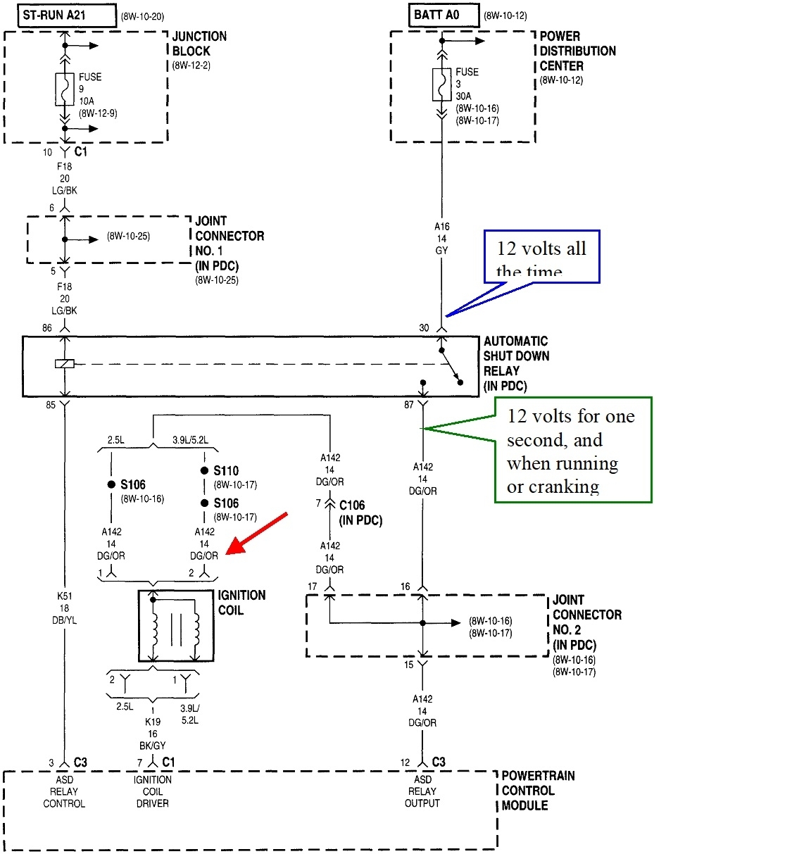
See if this helps. In the first diagram, I added a blue box to show there's 12 volts all the time to the ASD relay, and the green box shows where 12 volts appears during that first second when you turn on the ignition switch, then again during cranking or running. The red arrow is pointing to one of the places that switched 12 volts appears. That's at the ignition coil.

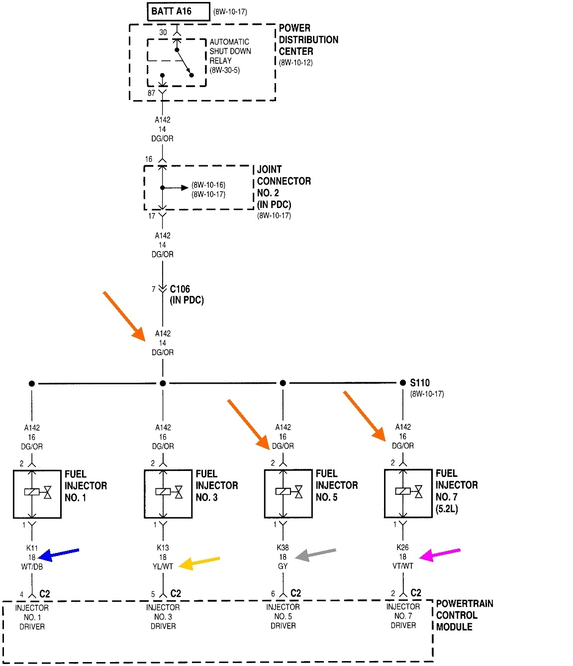
The second diagram shows four of the injectors and that the 12 volts appears at all of them at the same time, (red arrows). I also included the four other arrows, blue, yellow, gray, and pink, to show that each injector has its own individual control wire, and those are a different color at each connector.

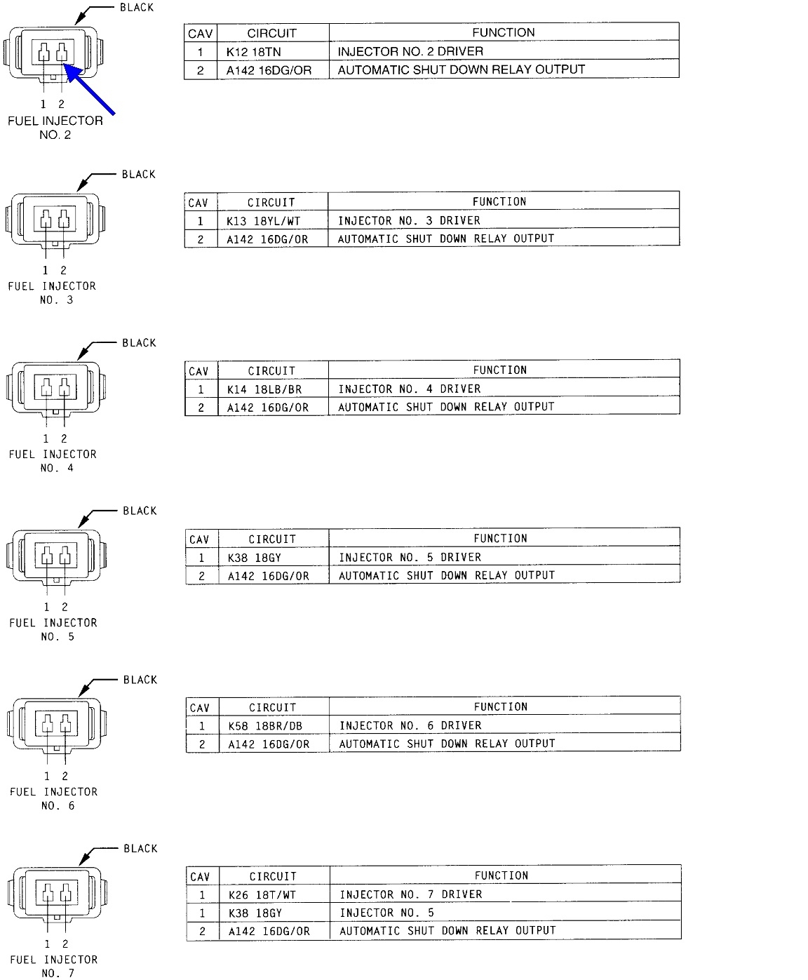
The third drawing shows six of the eight injector connectors. Of interest here is the same dark green / orange wire is in cavity number 2 in every connector. That is the one to test on in any of those connectors. I even added a nifty blue arrow pointing to it.
Aug 24, 2026 at 2:02 PM
Join 2CarPros for free, one of the most advanced car repair communities on the internet. From first-time drivers to seasoned mechanics, everyone is welcome to reply, share details, and get better answers. You can add a temporary image or video first; uploads are limited to 20 MB.
Ask a Free Question
Repair Safety Notice: This information is for general instructional purposes only. Vehicle repair can be dangerous. Verify all information, follow manufacturer service procedures, use proper tools and safety equipment, and consult a qualified repair shop when needed.