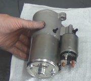
When I turn the key there is nothing, no crank, no start, no fuel pump?

Tiny
AL514
  • MECHANIC
  • 4,632 POSTS
No not necessarily, we just want to see if you have power going to relay 2 on the control side, we're just following the wiring diagram. Keep relay 1 out, this is only testing the power feed to both relays from the ignition switch to the control side of both relays, keep it simple like your last test, you said you had no power on Relay 2 pin 85.

With both relays out, Relay 2 should have at least one of its 4 pins with power.

Relay 1 pin 86 and Relay 2 pin 85 should also have no resistance between those two pins because they are supposed to be connected inside the fuse panel. They're fed by the same circuit.
Was this
answer
helpful?
Yes
No
Sunday, October 6th, 2024 AT 4:06 PM
Tiny
MANGOMIKE17
  • MEMBER
  • 42 POSTS
So, with both relays out relay 2 should have a pin with constant power, correct?
Was this
answer
helpful?
Yes
No
Sunday, October 6th, 2024 AT 5:01 PM
Tiny
MANGOMIKE17
  • MEMBER
  • 42 POSTS
Because currently I do not have constant power on any of the four pins for my theft relay number 2.
Was this
answer
helpful?
Yes
No
Sunday, October 6th, 2024 AT 5:01 PM
Tiny
AL514
  • MECHANIC
  • 4,632 POSTS
In Crank Relay 2 should have at least one pin thats hot. Remember the control power comes from the ignition switch.
Was this
answer
helpful?
Yes
No
Sunday, October 6th, 2024 AT 5:25 PM
Tiny
MANGOMIKE17
  • MEMBER
  • 42 POSTS
So, I do have power in crank on theft 2 relay but only 1 pin there isn't a constant power though.
Was this
answer
helpful?
Yes
No
Monday, October 7th, 2024 AT 4:56 AM
Tiny
AL514
  • MECHANIC
  • 4,632 POSTS
Okay, Theft Relay 2 wont have power until Relay 1 activates, Here Ive marked the power from the Battery in blue, and the Relay Grounds in green.

If you install Relay 1, and leave Relay 2 out you should now have power on two of the 4 pins while cranking. Pin 85 and Pin 30,

Power comes from Relay 1 through pin 87 and 30, then goes to Pin 30 of Relay 2 and out of pin 87 to the Starter trigger wire.

So if the PCM is not grounding the relays you will not have power on pin 30 of relay 2.
You will still only have power on one pin of relay 2 like you did in the last test.
Was this
answer
helpful?
Yes
No
Monday, October 7th, 2024 AT 11:19 AM
Tiny
AL514
  • MECHANIC
  • 4,632 POSTS
Did you find your issue?
Was this
answer
helpful?
Yes
No
Wednesday, October 9th, 2024 AT 11:11 AM
Tiny
MANGOMIKE17
  • MEMBER
  • 42 POSTS
No, I did get an OBD II reader today and it says verify that the ignition is on check if the scan tools OBD2 connector is securely connected to the vehicle's DLC verify that the vehicle is OBD2 compliant turn the ignition off wait for about 10 seconds and turn the ignition back to on and at the top it says failed to connect.
Was this
answer
helpful?
Yes
No
Thursday, October 10th, 2024 AT 8:49 PM
Tiny
MANGOMIKE17
  • MEMBER
  • 42 POSTS
So, in the crank position I only have power on pin 85 there is no power to pin 30 on relay 2.
Was this
answer
helpful?
Yes
No
Thursday, October 10th, 2024 AT 9:01 PM
Tiny
AL514
  • MECHANIC
  • 4,632 POSTS
And thats with the Relay 1 in correct? Power comes from relay 1 to relay 2 pin 30. If thats the case, and you have no communication with a scan tool, then the PCM is not powering up. Its not activating those 2 relays, power is coming from the ignition switch to the load side of the relays but because the PCM is not powering up, its not grounding the relays either to crank the car. So we will need to check powers and grounds at the PCM, so go over your wiring again, check every connector for any pushed in female pins, or loose pins that are not making good contact.
These are part of the PCMs diagrams, pages 1(top & bottom) and 4(top & bottom), they show most of the powers and grounds for the PCM, the wires should be load tested but for now you can check to make sure youre getting a full 12volts to these locations, I have to go out on an emergency call today, but will get back with you as soon as I can. At least we know whats going on now. Try to use a test light and meter for checking these as well.
Was this
answer
helpful?
Yes
No
Friday, October 11th, 2024 AT 9:11 AM
Tiny
MANGOMIKE17
  • MEMBER
  • 42 POSTS
And yes, I checked for power with the theft relay ones in and I have no power on pin 30 and I will try to go through as much as possible today and tomorrow.
Was this
answer
helpful?
Yes
No
Saturday, October 12th, 2024 AT 9:21 AM
Tiny
AL514
  • MECHANIC
  • 4,632 POSTS
Okay, if you want to verify the PCM is not pulling the relays to ground, Pin 85 (Relay 1) and Pin 86 (Relay 2) both circled in green here are both pulled to ground during Cranking, if you put a meter on either of them and going to battery negative, you should read close to zero volts while in the Crank position.
Meaning the PCM is pulling them to ground and there is no voltage drop from either of those pins to battery negative (ground). I dont think you will see that. If one or the other is being pulled down, but not both, then you most likely have a broken wire in the fuse/relay box that houses those two relays.

In some cases if you have a test light that is very low current, you can use that to test for the PCM grounding circuits, but you need to know how much current the test light you own uses, if you put a test light in series with your multimeter and change the leads over to the Amps or mA setting, you can see how much each test light uses for current. I have tested many test lights, and for example a Harbor Freight 12v test light pulls about 250mA of current, it has an incandescent bulb in it, but my snap on also has an incandescent bulb in it but it only uses 50mA so it is safe to use on PCM driver circuits, but the Harbor Freight test light I probably would not use on a PCM driver circuit such as a relay control wire. Thats why I recommended using the multimeter in that case.

You could hook a test light to B+ and go around and touch all the ground locations on the engine block and body/frame to see if they are all grounded. With an engine swap I'm sure you are just dealing with a wire connection issue if you didn't change out any of the fuse boxes or PCM, etc.
Was this
answer
helpful?
Yes
No
Saturday, October 12th, 2024 AT 12:08 PM
Tiny
MANGOMIKE17
  • MEMBER
  • 42 POSTS
AL514
MECHANIC4,579 POSTS
And thats with the Relay 1 in correct? Power comes from relay 1 to relay 2 pin 30. If thats the case, and you have no communication with a scan tool, then the PCM is not powering up. Its not activating those 2 relays, power is coming from the ignition switch to the load side of the relays but because the PCM is not powering up,

So I have constant power with the key off on relay 1 pin 30 but I have no constant power on relay 2 on any pin so then if I put it in the crank position I then have power on pin 85 and 30 on relay 1 and I have power to pin 85 on relay 2 in crank position but that is the only one that has any power going to it and it's only when it's in the crank position there is no constant power on relay 2 nor do I have any power on pin 30 on relay 2 at all during crank or not still fighting the same issues as before
Was this
answer
helpful?
Yes
No
Thursday, October 17th, 2024 AT 10:26 PM
Tiny
MANGOMIKE17
  • MEMBER
  • 42 POSTS
So it was brought to my attention that since the prnd321 is on constantly and there is no box around which gear it is in that it won't send a signal or something to the PCM to allow it to turn on they said it could still be my neutral safety switch but I bought a new one of those and replaced it to verify and it is still doing the same thing so it was not the neutral safety switch and the prnd321 light still does not go off and there still is no indicator light to indicate which gear it's in.
Was this
answer
helpful?
Yes
No
Thursday, October 17th, 2024 AT 10:28 PM
Tiny
MANGOMIKE17
  • MEMBER
  • 42 POSTS
I was also wondering and my under-hood fuse panel there are four mini fuses numbers 14 16 18 and 19 that do not have any power to them no matter if the key is in the crank position or in the on position is that normal? I am unsure on what these mini fuses are linked to or if they should have power to them when the vehicle is not running.
Was this
answer
helpful?
Yes
No
Thursday, October 17th, 2024 AT 10:33 PM
Tiny
AL514
  • MECHANIC
  • 4,632 POSTS
I will check on those fuses right now, as for the relay pins, remember power for pins 86(relay 1) and 85(relay 1) comes from the ignition switch (marked in Red here), so you would have power during crank from those pins. I'll post this diagram again; you should only have constant power on pin 87 of relay 1 with the key off. The two fuses on the right of the diagram come directly from the battery. Circled in Orange are the 2 pins that PCM should be pulling to ground to activate both relays at the same time.
Since this was an engine swap, and you didn't replace anything else than the engine, so you're using the old harness and fuse boxes, etc, it has to be a connection issue or a missing ground. The PNRD should not be on constantly either, it should power up when you turn the key to the On/Run position.
Was this
answer
helpful?
Yes
No
Friday, October 18th, 2024 AT 10:07 AM
Tiny
AL514
  • MECHANIC
  • 4,632 POSTS
Are there labels on those fuses, maybe on the under side of the fuse box lid? Service info does not show numbers, only what the fuse powers up, there should be a list in the fuse box, or the owners manual in the glove box has a list of each fuse.
Was this
answer
helpful?
Yes
No
Friday, October 18th, 2024 AT 10:09 AM
Tiny
AL514
  • MECHANIC
  • 4,632 POSTS
This is an example of the OEM power distribution fuse box, there are no numbers on either the aftermarket or OEM diagrams, I'm sure those fuses should be powered at some point.
Have you tried just checking for voltage drop from Battery Positive to each fuse under the hood? All of these fuses come directly from the battery, so they should all be hot, that includes part of the rear fuse box as well.
Was this
answer
helpful?
Yes
No
Friday, October 18th, 2024 AT 10:17 AM

Please login or register to post a reply.

Sponsored links