Here's how to test the camshaft position sensor also the crankshaft position sensor
OPERATION
The camshaft position sensor, or CMP sensor is located inside the distributor. The ECU uses the CMP signal to determine the position of the No. 1 cylinder piston during its power stroke. The ECU uses this information in conjunction with the crankshaft position sensor to determine spark timing among other things.
The CMP sensor contains a Hall effect device which sends either a 0.0 volt or a 5.0 volt signal to the ECU depending on the position of the distributor shaft.
If the cam signal is lost while the engine is running, the ECU will calculate spark timing based on the last CMP signal and the engine will continue to run. However, the engine will not run after it is shut off.
TESTING
Insert the positive (+) lead of a voltmeter into the blue wire at the distributor connector and the negative (-) lead into the gray/white wire at the distributor connector.
Do not unplug the distributor connector from the distributor. Insert the voltmeter leads into the back side of the connector to make contact with the terminals.
Set the voltmeter on the 15 volt AC scale and turn the ignition switch ON. The voltmeter should read approximately 5 volts. If there is no voltage, check the voltmeter leads for a good connection.
If there is still no voltage, remove the ECU and check for voltage at pin C-16 and ground with the harness connected. If there is still no voltage present, perform a vehicle test using tester M.S.1700, or equivalent.
If voltage is present, check for continuity between the blue wire at the distributor connector and pin C-16 at the ECU. If there is no continuity, repair the wire harness as necessary.
Check for continuity between the gray/white wire at the distributor connector and pin C-5 at the ECU. If there is no continuity, repair the wire harness as necessary.
Check for continuity between the black wire at the distributor connector and ground. If there is no continuity, repair the wire harness as necessary.
Crank the engine while observing the voltmeter; the needle should fluctuate back and forth while the engine is cranking. This verifies that the stator in the distributor is operating properly. If there is no sync pulse, stator replacement is necessary.

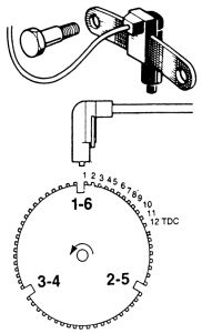
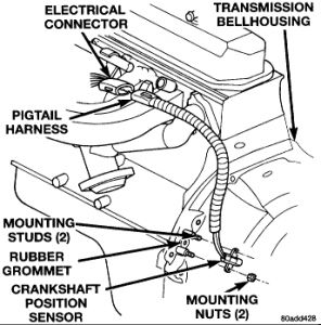
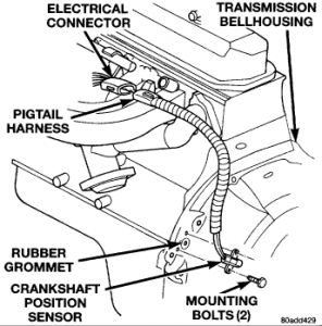
The Crankshaft Position Sensor (CKP) is secured by special shouldered bolts to the flywheel/drive plate housing. It is preset in its mounting at the factory and is non-adjustable in the field. The sensor senses TDC and engine speed by detecting the flywheel teeth as they pass during engine operation.
The flywheel has a large trigger tooth and notch located 12 small teeth before each Top Dead Center (TDC) position. When a small tooth and notch pass the magnet core in the sensor, the concentration and then collapse of the magnetic flux induces a small voltage spike into the sensor pickup coil winding. These small voltage spikes enable the ECU to count the teeth as they pass the sensor.
When a large trigger tooth and notch pass the magnet core in the sensor, the increased concentration/collapse of the magnetic flux induces a higher voltage spike into the pickup coil winding. This higher voltage spike indicates to the ECU that a piston will soon be at the TDC position 12 teeth later. The ignition timing for the cylinder is either advanced or retarded as necessary by the ECU according to the sensor inputs.
TESTING
Unplug the sensor connector from the ignition control module and connect an ohmmeter between terminals A and B as marked on the connector. The ohmmeter should read 125-275 ohms on a hot engine. Replace the sensor if the readings are not as stated.
Monday, December 7th, 2020 AT 9:36 AM
(Merged)


