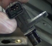
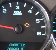
DTC P0342: CAMSHAFT POSITION (CMP) SENSOR CIRCUIT LOW
Diagnostic Aids
An intermittent may be caused by a poor connection, rubbed-through wire insulation or a broken wire inside insulation. Inspect harness connectors for backed-out terminals, improper mating, broken locks, improperly formed or damaged terminals, poor terminal-to-wire connection, and damaged harness. Disconnect PCM connector. Connect voltmeter to CMP signal circuit and wiggle harness and connectors. A change in voltage will indicate area of problem. If DTC cannot be duplicated, check scan tool FAILURE RECORDS to determine mileage since last DTC was set.
1. Perform On-Board Diagnostic (OBD) System Check. Read and record FREEZE FRAME and/or FAIL RECORDS data for each DTC set. Go to next step.
2. Turn ignition on. Using scan tool, read and record FAIL RECORDS data for DTC P0342. Operate vehicle within FAILURE RECORDS conditions. Using scan tool, read SPECIFIC DTC. If scan tool displays DTC P0342 FAILED THIS IGN, go to next step. If scan tool does not display DTC P0342 FAILED THIS IGN, check for an intermittent problem.
3. Disconnect CMP sensor. Turn ignition on. Measure voltage between sensor ground and CMP sensor harness connector voltage reference circuit (Brown and Yellow/Red wires on 3.2L, or Yellow/Red wires on 3.5L) and sensor ground. If reading is 4-6 volts, go to step 7. If reading is not 4-6 volts, go to next step.
4. Turn ignition off. Disconnect PCM and CMP sensor harness connectors. Check for poor connections at CMP sensor. If a problem is found, repair as necessary. Retest system. If no problem is found, go to next step.
5. Check for poor connection at PCM. If a problem is found, repair as necessary. Retest system. If no problem is found, go to next step.
6. Inspect CMP sensor voltage reference circuit (Brown and Yellow/Red wires on 3.2L, or Yellow/Red wire on 3.5L) for an open or short to ground. Inspect CMP sensor ground circuit for an open or short to power. Repair as necessary. Retest system.
7. With ignition on and engine off, measure voltage between CMP sensor signal circuit (Blue wire on 3.2L, or Blue and White wires on 3.5L) and sensor ground circuit at CMP sensor harness connector. If reading is not 4-6 volts, go to step 9. If reading is about 4-6 volts, go to next step.
8. Turn ignition off. Disconnect PCM harness connectors. Turn ignition on. Connect a voltmeter between ground and CMP sensor signal circuit (Blue wire on 3.2L, or Blue and White wires on 3.5L) at PCM harness connector. Monitor voltage while repeatedly touching CMP sensor signal circuit at CMP sensor connection with a test light to ground. If voltmeter displays voltage toggling between zero and 5 volts when test light is touched to CMP sensor signal circuit, leave voltmeter connected and go to step 12. If voltage is not as specified, go to next step.
9. Ensure PCM is still disconnected. Turn ignition on. Connect test light between battery voltage and CMP sensor signal circuit (Blue wire on 3.2L, or Blue and White wires on 3.5L) at PCM harness connector. If test light comes on, locate and repair short to ground in CMP signal circuit. Retest system. If test light does not come on, go to next step.
10. Probe CMP sensor signal circuit (Blue wire on 3.2L, or Blue and White wires on 3.5L) with a test light connected to ground. If test light comes on, locate and repair short to voltage in CMP sensor signal circuit. Retest system. If test light does not come on, go to next step.
11. Turn ignition off. Disconnect CMP sensor harness connector. Using an ohmmeter, check CMP sensor signal circuit (Blue wire on 3.2L, or Blue and White wires on 3.5L) for an open. If problem is found, repair as necessary. Retest system.
12. Remove CMP sensor and reconnect harness connector. Place a magnet on CMP sensor large enough to cover face of sensor. Observe voltmeter. If reading is about zero volts, go to next step. If reading is not about zero volts, replace CMP sensor. Retest system.
13. Reinstall CMP sensor, leaving voltmeter connected. Crank engine and observe voltmeter. If voltage toggles between zero and 4 volts, replace PCM. If voltage does not toggle between zero and 4 volts, replace faulty or missing CMP sensor magnet. Retest system.
Wednesday, July 7th, 2010 AT 2:06 PM


