Thank you for the donation.
Here are the diagnostic procedures for the codes.
DTC P1705/5: A/T GEAR POSITION SWITCH (SHORT)
NOTE:
DTC P1705 is set when PCM receives 2 gear position signals at the same time.
1. Using scan tool, retrieve freeze data. Clear DTCs and road test vehicle under same conditions freeze data was recorded. If DTC returns, go to next step. If DTC does not return, problem is intermittent. Check transaxle and PCM connections.
2. Turn ignition on. Observe gear position indicator lights while moving selector lever to each position. If any indicator light stays illuminated when selector lever is not in indicated position, go to next step. If gear position indicator lights illuminate in appropriate selector lever position, system is okay. Check for loose or damaged harness connectors.
3. Disconnect A/T gear position switch connector. If all A/T gear position switch indicators are not illuminated, replace A/T gear position switch. If any A/T gear position switch indicators are illuminated, go to next step.
4. Turn ignition off. Connect A/T gear position switch connector. Turn ignition on. Move selector lever through all positions except "R". Measure voltage between PCM harness connector "D" terminal No. 6 (White wire) and connector "B" terminal No. 20 or 22 (Brown/Black wires). If battery voltage is present, go to next step. If battery voltage is not present, inspect the following items. Repair as needed.
"� Check for short in wire between PCM harness connector "D" terminal No. 6 and A/T gear position indicator.
"� Inspect A/T gear position switch.
"� Check for continuity between PCM harness connector "B" terminal No. 20 and 22 and ground.
"� Check for loose PCM harness.
"� If no problems are found, replace PCM with a known-good unit and retest system.
5. Move selector lever through all positions except "N" and "P". Measure voltage between PCM harness connector "B" terminal No. 14 (Blue/White wire) and connector "B" terminal No. 20 or 22 (Brown/Black wires). If battery voltage is present, go to next step. If battery voltage is not present, inspect the following items. Repair as needed.
"� Check for short in wire between PCM harness connector "B" terminal No. 14 and A/T gear position switch.
"� Check for short in signal wire between A/T gear position switch and A/T gear position indicator.
"� Check for loose PCM harness connectors.
"� If no problems are found, replace PCM with a known-good unit and retest system.
6. Move selector lever through all positions except "D4". Measure voltage between PCM harness connector "D" terminal No. 9 (Yellow wire) and connector "B" terminal No. 20 or 22 (Brown/Black wires). If about 5 volts is present, go to next step. If about 5 volts is not present, inspect the following items. Repair as needed.
"� Check for short in wire between PCM harness connector "D" terminal No. 9 and A/T gear position switch.
"� Check for short in signal wire between A/T gear position switch and A/T gear position indicator.
"� Check for loose PCM harness connectors.
"� If no problems are found, replace PCM with a known-good unit and retest system.
7. Move selector lever through all positions except "D3". Measure voltage between PCM harness connector "D" terminal No. 8 (Pink wire) and PCM harness connector "B" terminal No. 20 or 22 (Brown/Black wires). If battery voltage is present, go to next step. If battery voltage is not present, inspect the following items. Repair as needed.
"� Check for short in wire between PCM harness connector "D" terminal No. 8 and A/T gear position switch.
"� Check for short in signal wire between A/T gear position switch and A/T gear position indicator.
"� Check for loose PCM harness connectors.
"� If no problems are found, replace PCM with a known-good unit and retest system.
8. Move selector lever through all positions except "2". Measure voltage between PCM harness connector "D" terminal No. 14 (Blue wire) and connector "B" terminal No. 20 or 22 (Brown/Black wires). If battery voltage is present, go to next step. If battery voltage is not present, inspect the following items. Repair as needed.
"� Check for short in wire between PCM harness connector "D" terminal No. 14 and A/T gear position switch.
"� Check for short in signal wire between A/T gear position switch and A/T gear position indicator.
"� Check for loose PCM harness connectors.
"� If no problems are found, replace PCM with a known-good unit and retest system.
9. Move selector lever through all positions except "1". Measure voltage between PCM harness connector "D" terminal No. 15 (Brown wire) and connector "B" terminal No. 20 or 22 (Brown/Black wires). If battery voltage is present, go to next step. If battery voltage is not present, inspect the following items. Repair as needed.
"� Check for short in wire between PCM harness connector "D" terminal No. 15 and A/T gear position switch.
"� Check for short in signal wire between A/T gear position switch and A/T gear position indicator.
"� Check for loose PCM harness connectors.
"� If no problems are found, replace PCM with a known-good unit and retest system.
10. Inspect PCM for loose connectors or damaged terminals. Repair as needed. If connectors are clean and tight, replace PCM with a known-good unit and retest system. If DTC P1705 is still present, repeat diagnostic procedure.
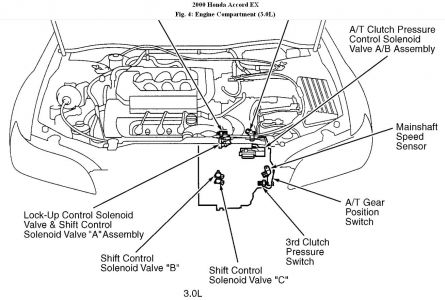
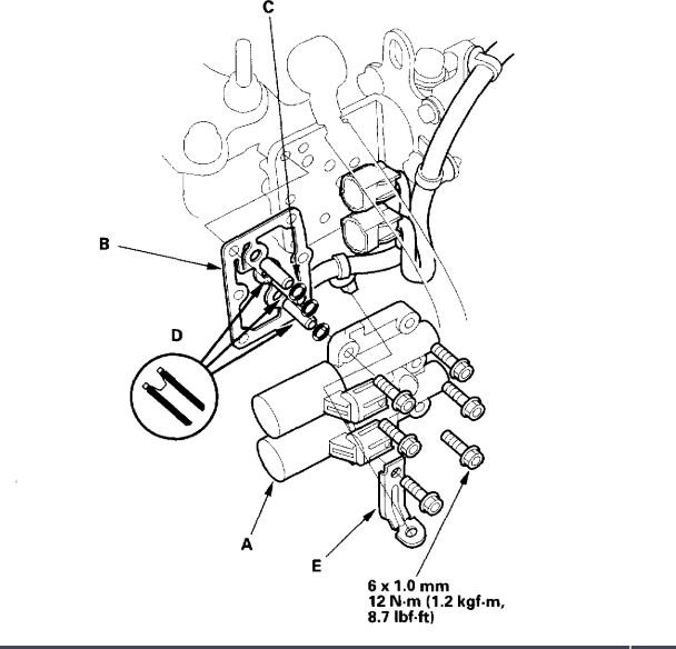
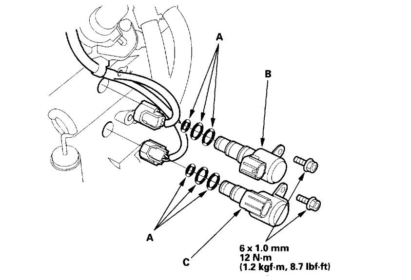
DTC P0758/8: SHIFT CONTROL SOLENOID VALVE "B"
1. Using scan tool, retrieve freeze data. Clear DTCs and road test vehicle under same conditions freeze data was recorded. If DTC returns, go to next step. If DTC does not return, problem is intermittent. Check transaxle and PCM connections.
2. Disconnect PCM harness connectors "B" and "D". Turn ignition on. Check for voltage between PCM harness connector "D" terminal No. 2 (Green/White wire) and connector "B" terminal No. 20 or 22 (Brown/Black wires). If voltage is not present, go to next step. If voltage is present, repair short to power in Green/White wire.
3. Turn ignition off. Measure resistance between PCM harness connector "D" terminal No. 2 (Green/White wire) and connector "B" terminal No. 20 or 22 (Brown/Black wires). If resistance is not 12-25 ohms, go to next step. If resistance is 12-25 ohms, go to step
7 .
4. Check for continuity between PCM harness connector "B" terminal No. 20 or 22 (Brown/Black wires) and ground. If continuity is not present, repair open Brown/Black wires. If continuity is present, go to next step.
5. Disconnect shift control solenoid valve "B" harness connector. Check for continuity between PCM harness connector "D" terminal No. 2 (Green/White wire) and connector "B" terminal No. 20 or 22 (Brown/Black wires). If continuity is not present, go to next step. If continuity is present, repair short to ground in green/White wire between PCM harness connector "B" and shift control solenoid valve "B".
6. Measure resistance between shift control solenoid valve "B" harness connector (solenoid side) terminals. If resistance is not 12-25 ohms, replace shift control solenoid valve "B". If resistance is 12-25 ohms, repair open in Green/White wire between shift control solenoid valve "B" and PCM harness connector or in Black wire between shift control solenoid valve "B" connector and ground.
7. Turn ignition on. Measure voltage between PCM harness connector "D" terminal No. 5 (Black/Yellow wire) and connector "B" terminal No. 20 or 22 (Brown/Black wires). If battery voltage is present, check for loose PCM harness connectors. Replace PCM with a known-good unit if necessary. If battery voltage is not present, check for blown fuse No. 6 (15-amp) in underdash fuse relay box. If fuse is okay, repair open between PCM harness connector "D" terminal No. 5 (Black/Yellow wire) and fuse relay box.
Was this helpful?
Yes
No
Monday, June 1st, 2020 AT 5:33 PM
(Merged)
