LOW OR NO CHARGE CONDITION
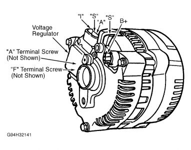
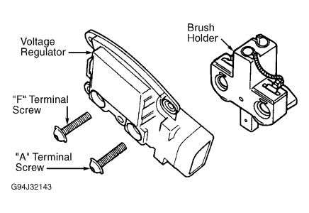
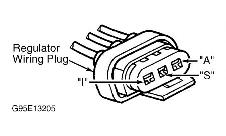
Unplug harness connector from regulator at rear of generator. Connect ohmmeter between regulator "A" and "F" terminal screws. See Fig. 1 and Fig. 3 . If resistance is not greater than 2.4 ohms, a short in field circuit or a grounded rotor coil is indicated. Replace generator. If resistance is greater than 2.4 ohms, go to next step.
Reconnect regulator wiring plug. Connect negative voltmeter lead to ground. Contact positive voltmeter lead to regulator "A" terminal screw. If voltmeter does not indicate battery voltage, repair open or high resistance in "A" circuit wiring. Perform load test after repairs.
If battery voltage is indicated at "A" terminal screw, ensure ignition switch is in OFF position. Connect positive voltmeter lead to regulator "F" terminal screw. If battery voltage is present, go to step 4). If battery voltage is not present, replace generator.
Turn ignition switch to ON position (engine off). With voltmeter negative lead to ground, contact positive lead of voltmeter to regulator "F" terminal screw. If voltmeter indicates 2 volts or less, go to next step. If voltage is greater than 2 volts, check circuit between "I" terminal and ignition switch. Repair if necessary. See "S" & "I" CIRCUIT TEST . If "I" circuit is okay, replace regulator. Perform LOAD TEST after repair.
Start engine and run at 2000 RPM with headlights on. Measure voltage at "B+" terminal of generator and at generator feed wire at starter relay. If voltage readings differ by more than 0.5 volt, repair high resistance or open in wire between "B+" terminal and junction near starter relay.
If generator still does not charge sufficiently, connect a jumper wire to regulator "F" terminal screw and ground it to rear housing. If output voltage increases to 13-15 volts, replace regulator. If output voltage does not increase to at least 13 volts, replace generator.


"S" & "I" CIRCUIT TEST
Unplug regulator 3-wire harness connector. Connect jumper wire from harness "A" terminal to regulator "A" terminal. See Fig. 1 and Fig. 2 . Connect another jumper wire from regulator "F" terminal screw to generator housing.
With engine idling, connect voltmeter negative lead to battery ground terminal. Connect voltmeter positive lead first to "S" terminal and then to "I" terminal of regulator harness connector. See Fig. 2 . Voltage at "S" terminal should be about 7 volts and about 14 v olts at "I" terminal. If "S" terminal and "I" voltages are okay, replace voltage regulator. Repeat LOAD TEST. If "S" and "I" circuit voltages are not as specified, go to next step.
If voltage is present at "S" terminal, but not 6-8 volts, replace generator. If no voltage is present at "S" terminal, disconnect one-wire connector ("S" terminal) on back of generator. See Fig. 1 . Check voltage at single "S" terminal. If about 7 volts are present repair "S" circuit wiring. If no voltage is present at single "S" terminal, replace generator.
If no voltage is present at "I" terminal, repair indicator light wiring circuit. Restore wiring connections and repeat LOAD TEST.

Sunday, January 18th, 2009 AT 9:45 PM


