CODE 14 - COOLANT TEMPERATURE SENSOR (SIGNAL VOLTAGE LOW) 1. Code 14 indicates control module has seen low coolant sensor voltage signal (high temperature) at control module terminal for a precalibrated period of time. This checks if conditions for Code 14 still exist. 2. This tests for grounded sensor signal line between control module and coolant sensor. Diagnostic Aids After engine is started, temperature should rise steadily to about 190 °F (88 °C) and then stabilize when thermostat opens. At normal operating temperature, signal voltage at control module terminal should be 1.5- 2.0 volts. Check sensor for shifted calibration by using sensor TEMPERATURE-TO-RESISTANCE VALUES table. When Code 14 is set, control module will turn on electric cooling fan(s) if equipped. CODE 14 ECM TERMINAL & CIRCUIT WIRING IDENTIFICATION TEMPERATURE-TO-RESISTANCE VALUES (1) Fig. 4: Code 14 Schematic (Signal Voltage Low) Coolant Temperature Sensor Fig. 5: Code 14 Flow Chart (Signal Voltage Low) Coolant Temperature Sensor NOTE: This chart assumes engine cooling system is functioning properly (not overheating). Test numbers refer to numbers on diagnostic chart. Application ECM Terminal Wire Color 3.1L "J" & "L" Bodies CTS Signal E16 Yellow CTS Ground B6 Purple 3.1L "W" Body (Exc. Calif.) CTS Signal C16 Yellow CTS Ground C10 Black 3.1L "W" Body (Calif.) CTS Signal A31 Yellow CTS Ground A17 Black Temperature °F ( °C) Ohms 210 (100) 185 160 (70) 450 100 (38) 1800 70 (20) 3400 20 (-7) 13,500 0 (-18) 25,000 -40 (-40) 100,700 (1) Measure resistance across sensor terminals. Page 1 of 1 TESTS W/CODES - 3.1L -1993 Chevrolet Lumina 8/9/2008
CODE 22 - THROTTLE POSITION SENSOR (SIGNAL VOLTAGE LOW) 1. This test checks if code is result of a hard failure or an intermittent condition. 2. This test simulates conditions for a Code 21. If control module recognizes change of state, control module and wiring are okay. 3. This simulates a high signal voltage to check for an open in TPS signal line to control module. Scan tester should recognize this signal and display high TPS voltage. Diagnostic Aids A scan tester displays throttle position in volts. Closed throttle voltage should be low. Voltage should increase gradually to about 4.5 volts at a steady rate as throttle angle is increased. If code is intermittent, see INTERMITTENTS in TESTS W/O CODES article in this section. CODE 22 ECM TERMINAL & CIRCUIT WIRING IDENTIFICATION Fig. 13: Code 22 Schematic (All Models) Throttle Position Sensor (Signal Voltage Low) Fig. 14: Code 22 Flow Chart (All Models) Throttle Position Sensor (Signal Voltage Low) NOTE: Test numbers refer to numbers on diagnostic chart. Application ECM Terminal Wire Color 3.1L "J" & "L" Bodies TPS Signal F13 Dark Blue TPS Ground B5 Black TPS Reference A5 Gray 3.1L "W" Body (Exc. Calif.) TPS Signal C15 Dark Blue TPS Ground C10 Black TPS Reference C12 Gray 3.1L "W" Body (Calif.) TPS Signal A30 Dark Blue TPS Ground A17 Black TPS Reference B31 Gray Page 1 of 1 TESTS W/CODES - 3.1L -1993 Chevrolet Lumina 8/9/2008
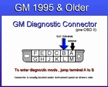
Try resetting the IAC: IDLE SPEED 1. Idle speed is ECM-controlled. Resetting of IAC valve pintle is the only possible adjustment. To reset IAC valve pintle position, turn ignition on (engine off). 2. Using a jumper, ground ALDL diagnostic test connector for 5 seconds. Remove jumper from ALDL diagnostic test connector. Turn ignition off for 10 seconds. Start engine, and check for proper idle operation. Refer to underhood emissions label for idle specifications. Clear any trouble codes. NOTE: Idle mixture is controlled by Electronic Control Module (ECM). Adjustment is not possible. NOTE: Incorrect idle speeds are normally caused by dirty throttle plate or vacuum leaks. Ensure all vacuum components are functioning properly. Page 1 of 1 ADJUSTMENTS - V6 -1993 Chevrolet Lumina 8/9/2008
Your TPS is not adjustable, so the only thing you can check is for voltage as you operate it by hand, low reading at idle to 4.5 volts at wide open.
Saturday, August 9th, 2008 AT 4:30 PM


