When the ignition is turned to the on position and the dash lights come on temporarily the check engine light does not come on?

2007 GMC YUKON
143,315 MILES • 5.3L • V8 • 2WD • AUTOMATIC
Avatar
JHARE213
  • MEMBER
  • 42 POSTS
When I put my scanner on the vehicle it doesn't show that any codes are stored so I don't know if there may be an issue or not. I am assuming that the light may be blown or disconnected somehow, is it possible that this light is controlled by a fuse?
Jun 19, 2023 at 12:11 PM
Repair Safety Notice: This information is for general instructional purposes only. Vehicle repair can be dangerous. Verify all information, follow manufacturer service procedures, use proper tools and safety equipment, and consult a qualified repair shop when needed.
Advertisement
Avatar
AL514
  • AUTOMOTIVE REPAIR CONTRIBUTOR
  • 5,479 POSTS
Hello, do you have communication with the engine computer (ECM)? and what scan tool are you using? The Check Engine light is an LED so it's most likely not a light issue, if a section of the ECM is not powering up the check engine light won't come on. Does the vehicle start? It's not on a fuse either, the signal comes from the ECM to the instrument cluster.
Are you noticing anything else missing on the Instrument Cluster?
Also, can you communicate with the Body Control Module?

https://www.2carpros.com/articles/how-a-car-computer-works-pcm-ecm-bcm

https://www.2carpros.com/articles/checking-a-service-engine-soon-or-check-engine-light-on-or-flashing
Jun 19, 2023 at 4:30 PM
Advertisement
Avatar
JHARE213
  • MEMBER
  • 42 POSTS
The scan tool is a Foxwell NT301. The vehicle starts and seems to run just fine. We just recently bought it so I am a little nervous that the seller could have done something trying to hide an issue to sell it.
Jun 19, 2023 at 4:50 PM
Avatar
AL514
  • AUTOMOTIVE REPAIR CONTRIBUTOR
  • 5,479 POSTS
Do you notice anything possibly taped over the Check Engine light? You may need a flashlight to take a real close look at the Cluster. But that light should come on at key on for at least 30 seconds.
Does that scan tool communicate with any other modules besides the ECM?
Jun 19, 2023 at 4:57 PM
Avatar
JHARE213
  • MEMBER
  • 42 POSTS
At turn on of the scanner it asks if I want to connect to the engine or A/T control module. If they put any tape on there I can't tell. I took a picture of the dash to show the lights that illuminate when the key is turned to the on position. Aside from the engine outline I can make out another light that doesn't illuminate, which I am guessing is for the traction control system. It is a car inside of a triangle with two squiggly lines beneath it.
Jun 19, 2023 at 5:08 PM
Avatar
AL514
  • AUTOMOTIVE REPAIR CONTRIBUTOR
  • 5,479 POSTS
You can try to get the engine computer to set a code, try unplugging an ignition coil while the engine is running, or a fuel injector, and the ECM should set a circuit code for that component, the Check engine light should come on right away when you unplug it, then shut the truck off with it still unplugged and turn the key back on and scan it for codes,
This is the ECM circuit to the Cluster for the MIL control.

Try this 30 second delay, after shutting the truck down.
Jun 19, 2023 at 5:21 PM
Avatar
JHARE213
  • MEMBER
  • 42 POSTS
Okay, I unplugged one of the ignition coils. The light didn't come on but the scanner did pick it up under the pending codes, instead of under the stored codes.
Jun 19, 2023 at 5:44 PM
Avatar
JHARE213
  • MEMBER
  • 42 POSTS
I plugged that coil back in and tried to crank the vehicle and now everything just shuts off like the battery is completely dead. I hope I didn't mess something up in the process.
Jun 19, 2023 at 5:50 PM
Avatar
AL514
  • AUTOMOTIVE REPAIR CONTRIBUTOR
  • 5,479 POSTS
No that should have just set a code, clear the code, then turn the key off for 30 seconds, and start it up. The light should have come on with that code, there is a TSB on wiring harness damage that I will post, it's for down near the E Brake for the harness that goes up to the Cluster, but somethings not right with that light not coming on.
Do you notice anything around the Data Link Connector where you plug the scan tool in? Something tells me there is a wiring issue with this vehicle.
Jun 19, 2023 at 6:11 PM
Avatar
AL514
  • AUTOMOTIVE REPAIR CONTRIBUTOR
  • 5,479 POSTS
So, it looks like you unplugged the number 1 Ignition coil on the driver side of the engine, and the ECM is on that side of the engine compartment, so it's possible there is a wiring issue that is on that side, there is a fuse panel, the ECM and TCM located there. I would check the ECM connectors, there are 2 of them, C1 and C2, the C1 connector has all the ignition feeds. As well the MIL light wire.
Here are all the connector pinouts for the ECM.
Jun 19, 2023 at 6:49 PM
Avatar
JHARE213
  • MEMBER
  • 42 POSTS
The only thing I noticed was the dlc is loose, looks like one of the bolts that fasten it to the dash is missing. I will inspect the wiring closely tomorrow when I get off from work.

I did let the vehicle sit for a few minutes and tried to crank it again. It turned over slowly then managed to crank up. I drove it around the block to allow the alternator to charge the battery some.
Jun 19, 2023 at 6:49 PM
Avatar
AL514
  • AUTOMOTIVE REPAIR CONTRIBUTOR
  • 5,479 POSTS
refresh this page, I posted the ECM connectors and pinout diagrams. Is it starting and stalling out, or just cranking over?
Jun 19, 2023 at 6:53 PM
Avatar
JHARE213
  • MEMBER
  • 42 POSTS
It finally started. It was acting like the battery had just completely drained.
Jun 19, 2023 at 6:57 PM
Avatar
AL514
  • AUTOMOTIVE REPAIR CONTRIBUTOR
  • 5,479 POSTS
Okay, I'm glad it got started, but I think possibly leaning over the ECM connectors and harness may have moved some of it around, this is exactly what happens with pin fitment issues.
The starting issue sounds like the ECM lost power. We unplug coils all the time when doing a power balance test, so there's no way that would cause a no start, if you have a multimeter and test light, we can start testing some power feeds to the fuse panel and ECM.

This splice circled in red looks like one of the main GM comb splice packs where all the modules connect together to the GM class 2 serial data network. There are a couple of them in the vehicle. Check that there are no pins that are loose or that the connector hasn't been messed with.
Jun 19, 2023 at 7:15 PM
Avatar
JHARE213
  • MEMBER
  • 42 POSTS
I have a multimeter but not a test light, I will pick one up on my way home from work tomorrow.
Jun 19, 2023 at 7:31 PM
Avatar
JHARE213
  • MEMBER
  • 42 POSTS
One other question, what would make the HVAC system blow cold air regardless of what you set the temperature to?
Jun 19, 2023 at 7:55 PM
Avatar
AL514
  • AUTOMOTIVE REPAIR CONTRIBUTOR
  • 5,479 POSTS
That can be either one of the hot/cold temperature Blend doors is stuck, it can be an issue with the control module not commanding the door to move, a bad temperature sensor, wiring issue.
I think we're going to find a connector issue with the problems you're having. For example, the ECM might be turning on the Check engine light, but if the circuit to the actual LED is not complete you won't see the light,
I have been seeing a lot of connector and pin fitment issues ever since it started to get warm this year. Certain things will happen common to a lot of different vehicles when the seasons change. The fact that you were able to trigger a code and read it tells me the ECM is up and working ok, as far as we know, but you're not getting the check engine light. But we can check these things right at the ECM connector to see if the signal is making it out of the computer, and if so, then we move down the circuit to find the area where it has a bad connection. If you had a more high-end scan tool you would be able to scan the HVAC control module and there is probably a code set in there too for whatever the issue is. But you need a scan tool that can do full system scans of every module in the vehicle.
Jun 20, 2023 at 12:29 PM
Avatar
JHARE213
  • MEMBER
  • 42 POSTS
Okay, for now I will focus on the ECM. I picked up a test light.
Jun 20, 2023 at 1:57 PM
Avatar
AL514
  • AUTOMOTIVE REPAIR CONTRIBUTOR
  • 5,479 POSTS
Okay, I would just check the C1 ECM connector first, since it has the Check Engine light wire in it. The connector is labelled as black, C2 is supposed to be Grey, they are not always correct on this. But you can go by wire colors too. Here's the pinouts for C1, pin 68 brown/white wire is the MIL control wire. But check all the pins, especially the ones in the 4th diagram, they have the ignition voltage, battery positive, etc. And the 5th diagram has the only Ground wire in this connector. Check for corrosion, any pins that are pushed back into the connector end, bent pins, things like that. Most of these also have a extra cover on the connector, so if you want to back probe any connectors while plugged in you will have to remove the cover. Make sure the key is off and out of the ignition. I would check that fuse panel and any Ground connections to the body while you're working in that area. If they look green or white with corrosion, they are no good. They don't put these modules and fuse boxes in the greatest places.
I think what happened yesterday when you unplugged that coil, since it was the number coil, I assume you leaned over the left hand side of the truck to unplug it? You may have pushed on some connector that is not in good shape. But see what you find with a visual inspection of all that. I will have to look up how the ECM controls the MIL light, if it grounds at pin 68 or if it sends power out to the cluster. Diagram 7,8 are from the Cluster section and 9,10 are from the ECM diagrams where it looks like the Cluster sends out Ignition On voltage and the ECM controls the Ground side of the circuit, but I am sure there are all kinds of connectors in between the 2.
Just don't use the Test light yet on checking the ECM, we have to be careful with it, some test lights pull too much current for specific ECM circuits. But we'll get to that. Do you know if it is an LED test light or Incandescent test light?
Jun 20, 2023 at 2:35 PM
Avatar
JHARE213
  • MEMBER
  • 42 POSTS
Okay, so, when I go to check the ECM module do I use the test light and touch each of the pins that you have highlighted?
Jun 20, 2023 at 4:53 PM
Avatar
JHARE213
  • MEMBER
  • 42 POSTS
I did lean over the left side of the SUV when I unplugged the ignition Coil, so it is entirely possible that I jostled something when I done that. Here is the test light I got not sure if it is LED or not.
Jun 20, 2023 at 5:03 PM
Avatar
JHARE213
  • MEMBER
  • 42 POSTS
So, I should use the multimeter instead then? Am I looking for a specific voltage?
Jun 20, 2023 at 5:22 PM
Avatar
AL514
  • AUTOMOTIVE REPAIR CONTRIBUTOR
  • 5,479 POSTS
No, I just wanted you to do a visual inspection of that ECM connector, checking to see if any of pins in the connector were pushed into the connector. Or if the ECM pins had corrosion on them or were bent. If someone else has been messing around with it before you bought the vehicle, they could have done anything. We haven't gotten to any voltage testing yet, because just unplugging that coil yesterday sent the vehicle into a no start condition, tells me that you leaned on, or pushed on a connector that caused that. Just the same as you not having a check engine light.
I just put the diagrams up to show how the circuit works and why you need to check the ECM C1 connector for pin fitment issues first.
Same with the Fuse box, does it have loose or corroded connectors?
Jun 20, 2023 at 6:24 PM
Avatar
JHARE213
  • MEMBER
  • 42 POSTS
Oh okay, I was putting the cart before the horse. I haven't thoroughly checked everything just yet, we had a storm roll in. But I did notice a large gray rectangular relay or fuse in the fuse box that appears to be plugged in where I don't think there is a connection, it's just sitting there loosely. I don't believe it is shown on the diagram, is it possible that it is a spare? It has the same numbers on it as 3 other relays/fuses. I know a lot of the fuses in the box look old and pretty dirty.
Jun 20, 2023 at 6:49 PM
Avatar
AL514
  • AUTOMOTIVE REPAIR CONTRIBUTOR
  • 5,479 POSTS
Okay, I'll take a look for the diagram of the fuse panel, as for that test light I can't tell if it is an LED or not, I don't think it is, If it has a regular little light bulb in it, then it's not a low current test light and you have to very careful testing computer driver circuits and pins, you can burn out a driver easily. You don't want to do that. I did some reading up on the MIL and the Cluster supplies voltage to the LED in the instrument panel and then the ECM grounds the other end to turn it on, so either the instrument cluster is not supplying that voltage, or there is a problem in the circuit further down. But there is a testing procedure, we will have to modify it somewhat because I don't think you have a scan too that can turn the MIL with a bidirectional command.

Diagram 1 is the Fuse block, i marked as many relays as I could find, there is a pinout list for each connector that's underneath, but not layout of the top of the fuse block.
Diagram 2 is the underside, with 6 main connectors, these connectors tend to get corroded because of location, water and stuff from the road splashes up, and that's what happens. So, if the fuses up top look dirty, imagine what those connectors look like. If you can unbolt the Fuse block and take a look at those connectors, you might find something.
Pins and wires break under fuse panels like this all the time. It causes relays to lose power or control. I have seen this happen many times. But pull out the relay that is just sitting there and see if there are any pins below, if not, then you know that someone else has been trying to fix this vehicle in the past and has had some type of electrical issues.
We can check the ECM connector tomorrow, or whenever, with it plugged in and back probe the pin 68 and see if the ECM pulls that circuit to Ground at just Key On to begin with. I'll explain how to do that with the multimeter, we will just check for voltage drop to the battery negative with the meter.

The connector C109 runs from the ECM under the Fuse Block to the Instrument Cluster, there's 2 different designs of this connector (diagram 3 and 5) but the pin A7 (Brown/White wire) is the same, this is the MIL command wire that gets grounded by the ECM to turn the MIL On. This connector should be checked as well. Its black, the 1st design has 38 wires, and the 2nd design has just 24. But it shouldn't be too difficult to find.
Jun 20, 2023 at 6:58 PM
Avatar
JHARE213
  • MEMBER
  • 42 POSTS
Okay, so, I unplugged the two connectors to the ECM and took pictures of the pins, none of the pins appear to be bent or have any corrosion that I can see.
Jun 24, 2023 at 4:04 PM
Avatar
JHARE213
  • MEMBER
  • 42 POSTS
Looking at the wires under the dash I don't see anything that stands out as unusual to me. A lot of the electrical wire wrap seems to have become "gooey" so to speak but I guess that can be attributed to the age of the vehicle. I pulled the cover down from around the hood latch to look at that connector you showed a picture of nothing really looks out of the ordinary although some of the wires could be pushed in a little, not quite like they are loose but just have a little play to them. The large gray fuse/relay I spoke of earlier is in the location where there is nothing shown on the diagram.
Jun 24, 2023 at 4:31 PM
Avatar
AL514
  • AUTOMOTIVE REPAIR CONTRIBUTOR
  • 5,479 POSTS
Are there any pins if you pull that relay out? or is it just sitting in empty holes?
There is nothing listed there for a relay (in red).
This connector is under that fuse block, there is 2 different designs, but it's not under the dash, it's a bulk connector that the check engine light control wire runs through.
Jun 24, 2023 at 5:53 PM
Avatar
JHARE213
  • MEMBER
  • 42 POSTS
Yeah, the relay appears to just be sitting in empty holes. Since that connector is under the fuse block, I need to unhook the block so I can reach the connector, right?
Jun 24, 2023 at 6:25 PM
Avatar
AL514
  • AUTOMOTIVE REPAIR CONTRIBUTOR
  • 5,479 POSTS
I'm not sure, there isn't a picture of it, for a location it just says under the fuse block. But I do see that of the 2 ECM connector locations you unplugged, the with the black plastic with the pins in it is the C1 connector that has the Check engine light control wire in it. If you want to skip that connector under the Fuse block, and check the ECM C1 connector, you will have to back probe the connector with a T pin and check with a multimeter what the circuit does from key Off to key On.
You might have to remove the outside cover of the connector to access the back of the wiring. But to test it, it will have to be plugged in, it's that or unplug the cluster harness plug and check it from there. It looks like it's only 4 screw to pull the cluster out and check it for power across 2 pins of the cluster connector. The 4th diagram is instructions for checking the power feed and ground to the cluster. You can check pin 18 for continuity to ground when you turn the key on for the next test. Pin 18 should be grounded by the ECM when the key is turned on and that's how the check engine light comes on. But I have a feeling it might be a circuit issue going to the ECM or an issue with the cluster itself. Just let me know what you want to test.
Jun 25, 2023 at 1:07 PM
Avatar
JHARE213
  • MEMBER
  • 42 POSTS
I will start going through this stuff this weekend, but I did pick up a mucar v06 bi-directional scanner so I can interact with more of the modules. Because it is bi-directional, I should be able to tell it to turn the light on, correct?
Jun 29, 2023 at 4:11 PM
Avatar
AL514
  • AUTOMOTIVE REPAIR CONTRIBUTOR
  • 5,479 POSTS
If it has that function, yes. Every aftermarket scan tool is different. That pin 68 should go to the ground when the key is turned on, if the bidirectional controls allow you to turn it on and nothing happens, you'll still have to diagnose the circuit. You can also try scanning the Cluster for any codes if you have access to every module now. There should be live data PIDs in each module that you can look at. But there's only really 3 possibilities, the PCM is not grounding pin 68, the cluster LED is burned out, or there's a circuit problem. Since you have other lights on the Cluster it's not an ignition voltage issue. I would suspect a pin fitment problem, which happens a lot when it gets to be summer. If you think about it, your car is sitting in the sun all day, the dash gets super-hot and these issues show up, we see a lot of different things when seasons change.
If you decide to back probe the PCM connector to check the circuit, you just have to be extra careful when doing it. If you're nervous about it, check the connector on the back of the cluster instead. It's only the 4 bolts.
Jun 30, 2023 at 11:20 AM
Avatar
JHARE213
  • MEMBER
  • 42 POSTS
Okay, so if I want to check it at the back of the PCM connector with a multimeter is the specific instructions on how to do so? Like how do I go about checking this wire, settings to use for the multimeter, result I am expecting to see? I am a little leery about pulling the cluster panel out just yet.
Jun 30, 2023 at 11:48 AM
Avatar
AL514
  • AUTOMOTIVE REPAIR CONTRIBUTOR
  • 5,479 POSTS
The recommended test for the MIL is at the Cluster connector, which really is not as difficult to pull out as you may think, once the 4 bolts/screws are out, the Cluster will pull right out and you can unplug the connectors at the back, Service info wants a test light in place of the MIL. And then command the MIL on with a scan tool and see if the PCM grounds that wire at the Cluster connector.
The other way, testing at the PCM connector, you will have to back probe the C1 connector on pin 68 while it's plugged in, (this can be the difficult part). There is usually a plastic cover on the PCM connectors that will have to be removed for testing, because you need access to the back of the connector's wiring.

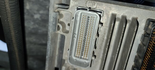
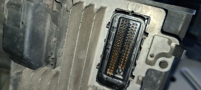
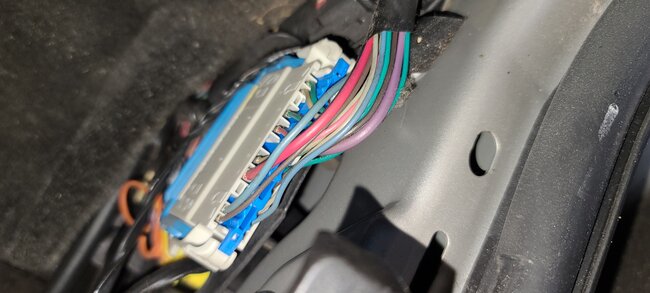
This plastic cover will have to come off of that Black connector, the one unplugged in your picture, Thats how you access the wiring, then you will have the wires exposed (diagram 2). And find pin 68 (6th diagram) is looking at the connector face, notice where pin 68 is, to the bottom of that notch in connector C1. It's a brown wire with a White stripe.

Diagrams 4 and 5 show some back probing pins, they have to be small enough to not damage the connector pin inside, You're just basically sliding the pin into the connector following the wire, not jamming into the wire.

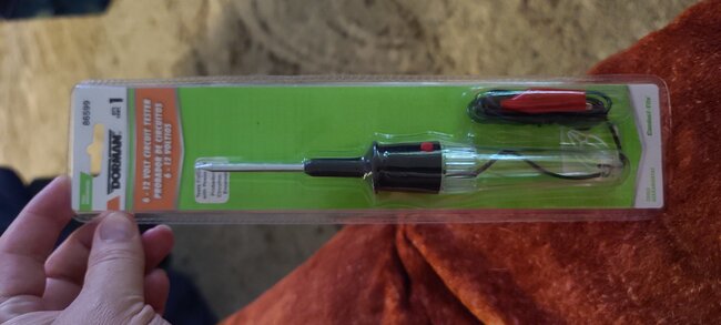
You can pierce the wire instead if you're more comfortable doing that, but you have to seal up the tiny hole afterwards. There is an example of a wire piercing tool in the 7th diagram, it's just making contact with the copper strains inside the insulation.

Either way, with your multimeter hooked to battery negative and the other lead touching the PCM wire, meter on DC volts. Once you turn the key on, the meter should read close to 0 volts, because the PCM is now closing the circuit to Ground (battery negative), And that's how the MIL comes on, the PCM just gives it a ground. The power feed comes from the Cluster ignition feed wire. If you read 12volts the entire time, then either the PCM is not grounding that pin, or there is an open circuit from that PCM pin 68 to the Cluster. Or the PCM has a failed circuit inside and is not able to complete the Ground circuit.

The test at the cluster is easier because you just need to unplug the connector and put a test light or multimeter in series with 2 pins of the Cluster connector and turn the key On. You won't have to be under the hood at all for that test. Diagrams 8 and 9 show how you don't need to really even command the MIL on, it should come on at just the key On, but the scan tool command on test will test the PCM driver for the MIL.

Just don't do any testing that you are not 100% sure on, you don't want to short the PCM out, especially since the vehicle runs, and this is just a light test. I would be more worried about the PCM back probing test than pulling the cluster, I have seen people cross pins while back probing connectors and shorting out the 2 pins together,
You can just leave it the way it is and scan for codes every once and awhile if you're not comfortable on these tests, I'd rather you do that if you're unsure.
Jun 30, 2023 at 1:44 PM
Avatar
JHARE213
  • MEMBER
  • 42 POSTS
Okay, I will start at the IPC. As long as I can find videos of what I am attempting I feel comfortable doing the task. It's not a real big deal for me to just do regular scans, but the light not coming on is bothering me, so I want to try and determine the cause and possibly fix it if it doesn't appear to be difficult.
Jun 30, 2023 at 7:43 PM
Avatar
AL514
  • AUTOMOTIVE REPAIR CONTRIBUTOR
  • 5,479 POSTS
You're just putting a test light in between 2 pins of the Cluster for each test. Then turning the key On. Thats all. If the PCM doesn't provide a ground, there's a wiring issue on the control wire or a bad PCM. You can look for videos.
Jul 1, 2023 at 9:29 AM
Avatar
JHARE213
  • MEMBER
  • 42 POSTS
I wasn't able to check the plug at the cluster, I need a tiny pin to stick in the holes, so I put everything back the way it was until I can come up with what I need to test it.
Jul 2, 2023 at 7:51 AM
Avatar
AL514
  • AUTOMOTIVE REPAIR CONTRIBUTOR
  • 5,479 POSTS
Just don't spread the connector pins on any connectors, using back probing pins on connectors is usually safer so no female pins get spread causing pin fitment issues afterwards.
Jul 2, 2023 at 1:07 PM
Avatar
JHARE213
  • MEMBER
  • 42 POSTS
Okay, I will see if they have smaller probes to back probe the connector at the auto parts store.
Jul 2, 2023 at 1:11 PM
Avatar
AL514
  • AUTOMOTIVE REPAIR CONTRIBUTOR
  • 5,479 POSTS
If you end up having to track this issue back to the PCM, you'll need back probing pins for other connectors as well. I don't think you're going to find the Cluster is missing the ignition feed since everything else works on it. So really the test #2 for pins 5 and 18 is the one that will tell you if the PCM is grounding the MIL bulb.
Jul 2, 2023 at 1:50 PM
Avatar
JHARE213
  • MEMBER
  • 42 POSTS
Okay, I used my higher end scanner on the vehicle and got a report after doing a scan that showed quite a bit of error codes.
Jul 8, 2023 at 3:58 PM