You're using a digital voltmeter to find what falsely appears to be 12 volts at the socket. Try using a test light instead, and you'll find 0 volts there. Unlike the meter which just measures the electrical pressure, (similar to measuring water pressure at the turned-off nozzle of a garden hose), the test light requires current flow through its bulb to work. Your circuit has a high resistance someplace that is preventing that current from getting through. This would be similar to standing on the garden hose and blocking it 99 percent closed. You'd still measure full pressure at the nozzle until you opened it and tried to get some water to flow.
When only one side is affected, the two most common places to find that high resistance is a burned contact inside the turn signal switch, and a corroded wire where someone spliced in a trailer wiring harness. That happens most often when someone used a Scotch-Lock connector. Those do not seal out moisture.
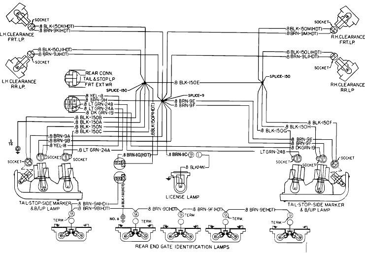
I took a guess at a C20 to find the engine size you listed. Here's the wiring diagram for the rear lights. Sorry that they did not include one with the signal switch. I'll try to read this one if you need help with that. As best I can tell, it's the yellow wire that is for the left rear brake and signal part of the bulb.
Image (Click to make bigger)
SPONSORED LINKS
Saturday, January 26th, 2019 AT 4:27 PM


