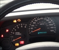
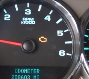
Many times it happens that a sensor signal is not being received by the computer and the repair man goes on to replace the sensor before performing a simple wire check.
If the computer continues to prompt code P0360, and thus no crank position sensor (CPS) is being received at the time of failure, it will be good to check the wiring: Here is how you should do it:
First inspect the connector and cables for damages, use contact cleaner to clean the CPS connector terminals with contact cleaner spray. Do the same with the Powertrain Control Module (PCM) connector number 1, its terminals and cables. Perform such visual inspection for the Camshaft Position Sensor three wire connector as both sensors share a couple of lines.
If that does not solve it, look for a faulty stranded cable in the CPS connection. To do that, follow this procedure:
1. Begin these tests with the battery connected, Power-train Control Module connectors connected, Crankshaft Position Sensor three wire connector plugged, and Camshaft Position Sensor three wire connector connected. Measure voltage between orange line of the Crankshaft Position Sensor (pin three of its connector) and ground. Voltage should be five volts, if higher PCM is at fault. If lower than five volts, suspect a short to ground. To find where the short to ground is, perform the following steps orderly.
2. Disconnect battery cable (negative), then disconnect (possitive) cable.
3. Locate line connector one in the PCM, unplug it.
4. In that connector locate wire A4, this is a brown/yellow line (that is brown color with a yellow stripe).
5. Measure continuity with an ohmmeter from that point to a good body frame ground. If continuity resistance is low, this could be considered a faulty short to ground of a line that was not designed to touch ground. If so, proceed accordingly. If not, continue to step five.
6. Unplug the three line connector of the Crankshaft Position Sensor.
7. Locate wire number two, again this is a brown/yellow line.
8. Measure continuity with an ohmmeter between this point and PCM connector one, pin A4. If resistance is high, then you have identified an open wire, and should proceed accordingly. If not follow to step nine.
9. Measure continuity with an ohmmeter between Crankshaft Position Sensor connector pin 2 and a good body frame ground. If resistance is low, then you have identified a short to ground, that line has not been designed to connect to ground, so you should proceed accordingly. If not follow to step ten.
10. Locate pin 2 of the Camshaft Position Sensor (CPS) and pin A4 of the PCM connector 1. This is a brown line with a yellow tracer. Perform a continuity test between both pins with an ohmmeter. If resistance is high then you have found an open wire and should proceed accordingly. If not follow to step eleven.
11. Connect an ohmmeter between pin 2 of the CPS connector and a good known body frame ground. If resistance is low, you have identified a faulty short to ground as this line has not bee designed to touch ground. If so, proceed accordingly. If not, follow to step eleven.
12. In the PCM connector, 1 locate pin A8 (gray line with a black tracer). Locate the same line color in the Crankshaft Position Sensor connector, pin 1. Perform a continuity test between both pins by using an ohmmeter. If resistance is high, then there an open wire which should be repaired. If not, proceed to step thirteen.
13. Touch pin A8 with an ohmmeter lead, and with the other ohmmeter lead touch a good known ground body frame connection. If resistance is low, then such line has a faulty short to ground as it was not designed to touch ground. If so, proceed accordingly. If not, continue to step fourteen.
14. Measure continuity between pin two of both sensor plugs: the Camshaft Position Sensor’s and the Crankshaft Position Sensor’s. If resistance is high then there is an open wire which should be repaired accordingly. If not, then all these wires have been tested okay and the fault should be traced somewhere else.
Monday, July 11th, 2011 AT 9:11 PM


