Normally all voltages are taken with respect to ground, meaning the voltmeter's black ground lead or the test light's ground clip go to the battery's negative post or to any paint-free part of the body or engine. They're all tied together electrically. There are some electrical tests that are taken with the tester's ground clip or probe connected to the battery positive post when we're looking for, (testing for) a ground issue, but in those cases it will always be indicated very clearly that you need to move that probe. As a former teacher, I know how there will always be someone who can misinterpret the best-written directions, so I work especially hard to make mine clear. The problem here is I don't have the luxury of knowing how much you already know or how brilliant you have become thanks to my wondrous instruction, so be sure to ask when something isn't clear.
I've gone done the wrong road many times in tv repair and car repair when I got false readings during a test, so one thing I always do out of habit is to "test my tester" to be sure it is working correctly. In this case, you have the ground lead or probe connected to ground, then, as a test, touch the positive probe to the battery's positive post. The light must light up and the voltmeter must show full battery voltage, typically 12.6 volts. About half of the time that won't happen until you scratch around what's hooked to the negative post. There's lots of corrosion on that lead cable clamp and the probe has to bite through that. The same thing commonly happens with jumper cables, and that renders them ineffective.
When your tester indicates 12 volts, you know the ground clip or probe has to making a good contact, so now when you take a reading at some other point, you can have confidence that it's right.
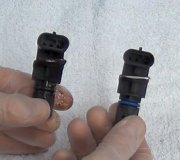
An even faster way to test your tester, in your case, is to measure the voltage on the yellow wire in the generator's plug. That one must have full battery voltage, (12+ volts), all the time. For more accuracy in this type of circuit, you can take the voltage readings with the connector still plugged in by back-probing through the rubber seals the wires go through. Don't worry now about the third wire which is white. You must have 12 volts on the yellow one, and you're supposed to find around 2 volts on the green / red one with the engine not running, and near 14 volts with the engine running.
Remember I said earlier you would find 12 volts on the green / red wire but that was with the connector unplugged. With it plugged in, there will normally be around 2 volts there until the system starts working. When the engine is running and making the magnet inside the generator spin, that's when the output is generated, and it's when the regulator PUTS full charging voltage onto the green / red wire to turn the warning light off.
Thursday, November 6th, 2014 AT 7:28 PM


