Introduction
Brake lights are a critical safety feature in every vehicle, alerting drivers behind you when you are slowing down or stopping. Understanding how brake light systems work can help in diagnosing issues and performing maintenance. A brake lighting system is a simple "on and off" circuit which is controlled by the driver when the brake pedal is pressed down. This guide will delve into the technical aspects of automotive brake light systems and provide a detailed step-by-step explanation of it's functionality.
The brake light system comprises several components:
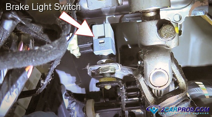
- Brake Light Switch: Typically located near the brake pedal, this switch activates the brake lights when the pedal is pressed.
- BCM or Lighting Control Module: These devices are used to output voltage to the brake lights.
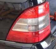
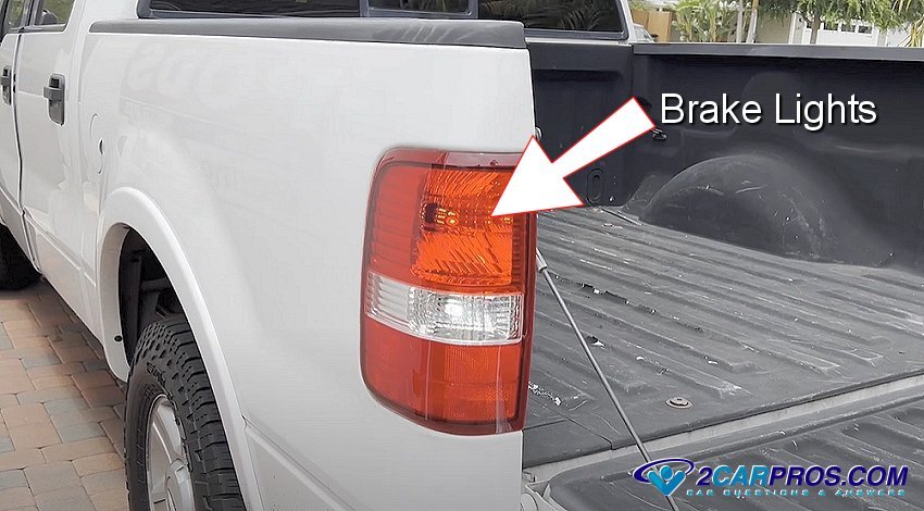
- Brake Lights: The bulbs or LEDs located at the rear of the vehicle that illuminate to signal braking.
- Wiring Harness: Connects the brake light switch to the brake lights, transmitting the electrical signal.
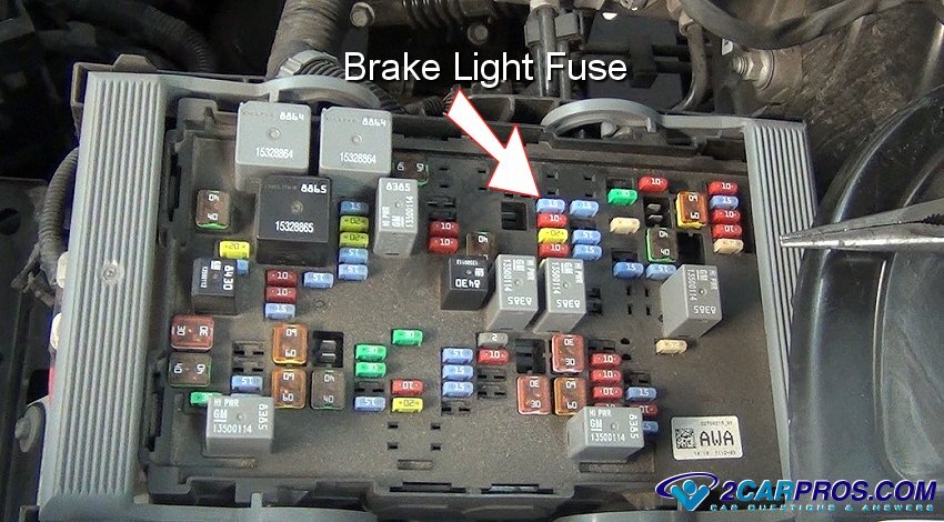
- Fuse: Protects the brake light circuit from electrical problems such as a short circuit.
- Ground Connection: Completes the electrical circuit, allowing current to flow throughout the system.
1. Everything begins with the brake light switch, when the driver of the car decides to slow down or stop the brake pedal is pushed which activates the brake light switch that connects the circuit that activates the brake lights. This control switch is located under the dash at the upper end of the brake pedal arm and is a low amperage "trigger" switch that simply connects the signal to tell the BCM (body control module) or LCM (lighting control module) to turn the brake lights on, older cars do not use a BCM or a LCM. Note: This brake light signal is used for ABS and traction control systems as well.
2. Once the BCM or lighting control module receives the signal from the brake light switch, output voltage is supplied to the brake light wiring circuit which illuminates the brake light bulbs. A simple wiring circuit is connected from the car's BCM and then onto the rear brake lamps.
3. A fuse or series of fuses are used to protect the wiring and computer circuits in the event of the short in the wiring or lighting socket. These fuses can be located in the PDC under the hood or in the interior fuse panel which is usually under the dash on the drivers side.
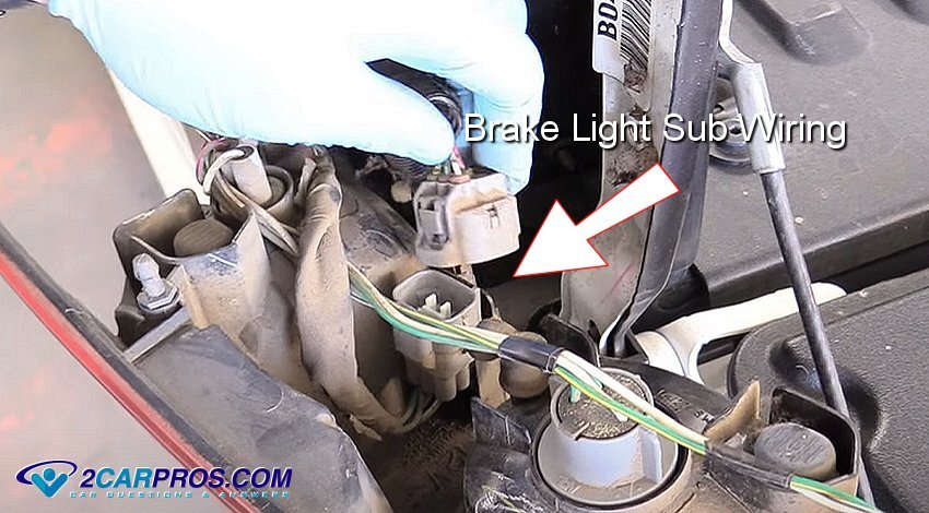
4. A brake light wiring harness is used to transfer the voltage from the firewall of the vehicle to the rear lighting systems, this harness is routed along the frame in a safe manner as to not come in contact with moving or rotating parts such as a driveshaft. There can also be a sub harness form the brake light lens which is plugged into the main wiring harness.
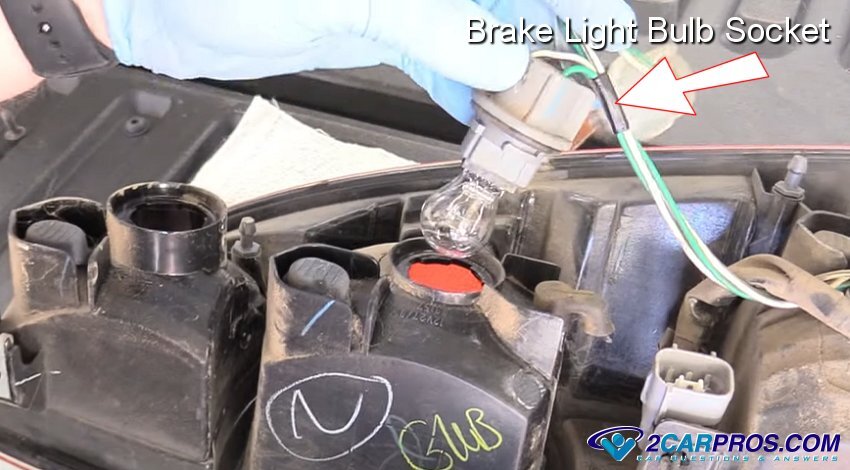
5. Light bulb sockets are spring loaded and are used to hold the brake lamp in place while providing a good power and ground connections. Some vehicles use a multi bulb plate which holds the running light, reverse light and brake light bulbs together.
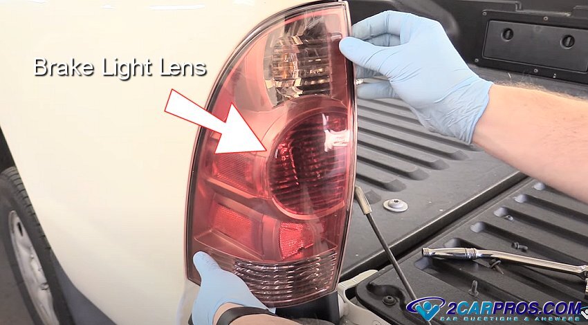
6. This bulb is fitted inside the brake light lens which is then mounted the vehicle via mounting screws. The lens is used to amplify the light source form the bulb when illuminated for better visibility.
7. LED brake light bulbs work on the same principle as regular filament bulbs but instead of going directly into the LED brake light bulb, the 12 volt feed it converter into a lower voltage, (between 2 and 4 volts). When the current flows through the filament in an incandescent bulb, it heats up and emits light. In the case of LEDs, the current passes through a semiconductor, emitting photons (light) as a result.
8. The grounding circuit of the brake light system is equally as important as the power circuit, when this connection failed the brake light will be dim, or not work at all.
More Information
In older vehicles the brake light switch connects 12 volt power to the brake lights directly and is protected by a fuse. These brake light switches can have more than two wires, which send signals to various additional controls in the vehicle such as the cruise control, ABS, traction control and shift-lock controls.
American made vehicles incorporate the car's blinker system into the brake light circuit. When the turn signal switch is operated the brake light circuit is substituted for the turn signal circuit for either right or left directional signals. European and Japanese cars have a separate light, (and circuit) for the brake and turn signal lights.
What Goes Wrong?
The most simple of all brake light problems is the fact that the bulbs simply burn out, this is an quick and easy fix in most cases. As in any electrical system an open or short circuit can occur interrupting the operation of one or all of the brake lamps. Lack of power to the brake lights can include:
- Burned out brake light bulb
- Blown brake light fuse
- Broken wire in the harness
- Poor connection at the bulb socket
- Body control module (BCM) failure
- Brake light switch not working
- Turn signal or multi-function switch failure
Through time and usage, the contacts inside the brake light switch can become worn and burn out rendering the switch non operational. A bad ground in the system can cause the electrical current to back feed which makes the bulb dim or dull. A poor connection at the bulb will make it flicker.
Credits
This guide knowledge base was created by the 2CarPros Team, and by Ken Lavacot: Automobile repair shop owner and certified master automobile technician of over 30 years. If you have question or need help please ask one of our experts we are happy to help. Please visit our 2CarPros YouTube Channel.

Article published 2024-06-26