Jun 10, 2025 at 6:51 PM
Will not start the fuel pump was not getting power?
2007 HONDA ACCORD
Advertisement
It's a key not a key fob. I actually have a diagnostic scanner at my disposal now and another thing that my old lady pointed out to me that I hadn't noticed until now is it for whatever reason her dash lights are on all the time. the car is off there's no key anywhere near the car and her dash lights are on constantly not sure what could be causing this.
Also the radio is in code mode if there was something we were going to try with that I just remember you mentioning needing the radio code also the scanner was unable to communicate.
Image (Click to enlarge)
Jun 10, 2025 at 6:58 PM
Also when i checked the 7 and 14 on the data plug or whatever it's called, the 7 read 10.86, the 14 read less than 5 when i used the 4or the 5 as ground there was no change.
Jun 11, 2025 at 8:21 AM
When I disconnected the ECM and immobilizer and checked for continuity there was none. My understanding is correct that means the ECM and the immobilizer at the ignition need to be replaced. I understand that they need to be replaced together so that they're paired around to pay someone extra to pair them together. I also going to have to replace the keys and do I need keys that have never been programmed before this is my last and final question thank you so much for your help I will be sure to donate to your GoFundMe and recommend you to everyone I know that has vehicle problems and needs assistance.
Jun 11, 2025 at 9:19 AM


Before you go replacing anything yet. When you unplugged the Immobilizer and ECM, then checked for continuity from the Immobilizer connector pin 2 and the ECM connector E pin 27, it's a red/blue wire you had no continuity? If you read OL on your meter when checking the resistance between these two pins, then there is an open circuit between the Immobilizer and ECM. You don't need to replace modules for an open wire. Replacing modules is the last thing you want to do, always verify your test results first, what if you go replace those modules, reprogram everything, along with new keys and the same issues still exists. This is the test where you need to have a resistance reading (continuity). Technically less than 5 ohms. If this circuit is open, more than likely there are other wires damaged as well.
Image (Click to enlarge)
Professional Diagram for 2CarPros Members
Click here to log in and view diagram.
Click here to log in and view diagram.
Jun 11, 2025 at 12:38 PM
Okay, so yes it read ol so that means there is a short somewhere we need to find?
Jun 11, 2025 at 12:41 PM
No there is an open circuit, a broken wire. You're checking on the red wire with a blue stripe, correct?
Jun 11, 2025 at 12:52 PM
Yes.
Jun 11, 2025 at 12:54 PM
So in between the Immobilizer and ECM is this junction connector C406, that's where you need to go next, check continuity from the Immobilizer connector pin 2 to C406, it's still going to be the same color wire going in and coming out of the connector. Check both. Let me see if there's any procedure for removing the knee panel there below that vent, in some cases there is an air bag located there.
Images (Click to enlarge)
Professional Diagram for 2CarPros Members
Click here to log in and view diagram.
Click here to log in and view diagram.
Professional Diagram for 2CarPros Members
Click here to log in and view diagram.
Click here to log in and view diagram.
Jun 11, 2025 at 1:05 PM
If the battery has been disconnected for a while already then, you're okay, I don't see any airbag in that location, but disconnecting the battery and letting the system discharge only takes about 3-5 minutes. But C406 looks to just be a junction bus bar type connector, where it simply connects the two wires when the two connectors are plugged in. If you have any water leaks it looks to be a location where water intrusion might be an issue, but you'll have to check it. You should have continuity from one red/blue wire D2 to the other E2. And also check for continuity from the Immobilizer connector to C406 as well. We're basically tracing the circuit back to locate the open.
Images (Click to enlarge)
Professional Diagram for 2CarPros Members
Click here to log in and view diagram.
Click here to log in and view diagram.
Professional Diagram for 2CarPros Members
Click here to log in and view diagram.
Click here to log in and view diagram.
Jun 11, 2025 at 1:26 PM
I just realized the Data Link connector "DIAG" wire runs through C406 as well, I'm wondering if that's why there are issues with the scan tool as well.
Image (Click to enlarge)
Professional Diagram for 2CarPros Members
Click here to log in and view diagram.
Click here to log in and view diagram.
Jun 11, 2025 at 1:34 PM
The 10.86volts on pin 7 might be correct, it could be an 11volt signal, or the multimeter is not fast enough to read the signal so it's just giving an average of voltage its reading, since pin 7 looks to be the K-Line which would be scan tool communications.
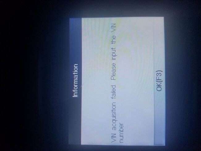
you weren't able to manually put the VIN in either?
you weren't able to manually put the VIN in either?
Jun 11, 2025 at 1:40 PM
But when I manually input the van, it told me what kind of vehicle it was, but it still wouldn't scan or give me any kind of other information unless there was something else, I could have done that I didn't do.
Jun 11, 2025 at 1:47 PM
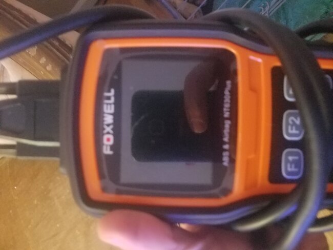
What scan tool are you using? It should have read the VIN pretty quick and give you access to scan at least the ECM if it's a basic OBD2 scan tool.
Jun 11, 2025 at 1:49 PM
Still would not connect to the car.
Image (Click to enlarge)
Jun 11, 2025 at 2:14 PM
Did you check pin 16 of the data link connector for power yet? It's the pin that powers up a scan tool.
Image (Click to enlarge)
Professional Diagram for 2CarPros Members
Click here to log in and view diagram.
Click here to log in and view diagram.
Jun 11, 2025 at 8:00 PM
You obviously have a wiring issue, go check C406 for any issues. Forget the scan tool until you find the wiring issue between the Immobilizer and ECM.
Jun 11, 2025 at 8:01 PM
I went back through I went back through and retested there is .5 ohms of continuity between the immobilizer and ecu and there is .3 ohms between the c406 and the immobilizer and between the D2 and E2 there is .3 ohms.
Jun 19, 2025 at 5:20 PM
I went back and retested the continuity because I wasn't sure if i had done it right. And apparently, I hadn't, so what now?
Jun 19, 2025 at 5:22 PM
Okay, I had to go back and see where you are at by this point, so with the meter set on Ohms (resistance) setting, you have continuity between the ECM E27 connector/pin and the Immobilizer connector pin 2 red/blue wire? This would run through the C406 connector plugged in.
I did see the very low voltage readings on the video with the test light, I saw 7 and 8 volts at some points, then 11 at some other fuses. That low voltage is going to be an issue that needs to be resolved first and will most likely take care of the starting issue. With the immobilizer flashing, the ECM is disabling the injectors from firing as a security measure. And I would get the battery charged up, testing with the key on is only going to cause it to drop lower and not help with getting accurate readings. I keep a battery maintainer on when doing diagnostics that require the key to be On for long periods such as this.
The static (at rest) battery voltage should be at least 12.6v when testing. This is because by the time the voltage gets to the ECM going through connectors it will drop lower due to voltage drop on connectors which is normal.
***But you want to see what fuses are reading that low 7 and 8 volts in that under hood fuse box to start with, write down which fuses have low voltage, so we know what circuits to focus our attention on. Once we know the fuses that are low, we can go through the power distribution wiring diagrams and see where the power for those specific fuses comes from and start to track down their trouble areas. Also make sure the battery terminals are clean and tight. You would be surprised by the amount of voltage drop that can happen from the battery post itself and the harness terminal its connected to.
Another issue here you mentioned is the cluster being on all the time, I didn't see it on in the video where you turned the key On, and then cranked it. I did see the wrench light (check engine light) come on for a few seconds there, but also the flashing Key. So has the cluster issue gone away? If it's still staying on now, that will run the battery down even faster when trying to test these fuses. I'd say that low voltage is most likely going to be the problem here, modules can't fully turn on and communicate with voltage that low.
Image (Click to enlarge)
Professional Diagram for 2CarPros Members
Click here to log in and view diagram.
Click here to log in and view diagram.
Jun 20, 2025 at 6:50 AM
Cluster issue not a problem now. I will put battery on charge this am and once it is charged go back and check voltage on all fuses under the hood and write down what the low ones belong too and post it when finished.
Jun 20, 2025 at 6:56 AM
Okay, sounds good. You will probably find some fuses in the dash fuse panel have low voltage too, but that is most likely just going to be from the under-hood fuses being low feeding the interior fuse panel.
These are the Power Distribution diagrams, just pages 1(top and bottom) and 3 for now since they have the Under Hood fuse box fuses and relays, so you can see where the low voltage fuses go to.
These are the Power Distribution diagrams, just pages 1(top and bottom) and 3 for now since they have the Under Hood fuse box fuses and relays, so you can see where the low voltage fuses go to.
Images (Click to enlarge)
Professional Diagram for 2CarPros Members
Click here to log in and view diagram.
Click here to log in and view diagram.
Professional Diagram for 2CarPros Members
Click here to log in and view diagram.
Click here to log in and view diagram.
Professional Diagram for 2CarPros Members
Click here to log in and view diagram.
Click here to log in and view diagram.
Professional Diagram for 2CarPros Members
Click here to log in and view diagram.
Click here to log in and view diagram.
Jun 20, 2025 at 8:07 AM
What happened that the cluster is not an issue now?
Jun 20, 2025 at 8:08 AM
Not sure I only witnessed it the time it was brought to my attention and since then I haven't seen it happen again.
Jun 21, 2025 at 1:46 PM
I'm attaching the video of the fuses under the hood that showed no voltage and the corresponding label for them on the diagram underneath the lid.
Jun 21, 2025 at 1:50 PM
So working from left to right the first 10amp is labeled- L-H/L LO
The second 10 amp is labeled L-H/L HI followed by the 15-amp fuse showing 12.5v and then two more 10 amps the first labeled R-H/L HI & the next and final fuse showing 0v labeled as R-H/L LO. also, I am a novice when it comes to some of this how would I go about testing the relays for
The second 10 amp is labeled L-H/L HI followed by the 15-amp fuse showing 12.5v and then two more 10 amps the first labeled R-H/L HI & the next and final fuse showing 0v labeled as R-H/L LO. also, I am a novice when it comes to some of this how would I go about testing the relays for
Jun 21, 2025 at 2:04 PM
So working from left to right the first 10amp is labeled- L-H/L LO
the second 10 amp is labeled L-H/L HI followed by the 15 amp fuse showing 12.5v and then two more 10 amps the first labeled R-H/L HI & the next and final fuse showing 0v labeled as R-H/L LO. also I am a novice when it comes to some of this how would I go about testing the relays for
the second 10 amp is labeled L-H/L HI followed by the 15 amp fuse showing 12.5v and then two more 10 amps the first labeled R-H/L HI & the next and final fuse showing 0v labeled as R-H/L LO. also I am a novice when it comes to some of this how would I go about testing the relays for
Jun 21, 2025 at 2:04 PM
The video isn't uploading for some reason.
Jun 21, 2025 at 2:06 PM
Did you check the fuses with the key On? Im going to just post a diagram of the under hood fuse box for you and you can explain which have low voltage by that. Which fuses were showing the low 7 or 8volt readings I saw on the other video, those are the ones we should be concerned with.
Jun 21, 2025 at 4:09 PM
This is the Under Hood fuse box and its fuse/relay labels, you can see most of the ones you referred to were for the Head lamps. Left and Right (high beam) or (low beam).
Images (Click to enlarge)
Professional Diagram for 2CarPros Members
Click here to log in and view diagram.
Click here to log in and view diagram.
Professional Diagram for 2CarPros Members
Click here to log in and view diagram.
Click here to log in and view diagram.
Jun 21, 2025 at 4:14 PM
I can't see which fuses you are on in the video that are reading 8 volts.
Correct me if I'm wrong, but it appears that you move to the 15amp fuse in the video and it's the first one to read low voltage, below 9 volts, and that 15amp blue fuse (#4) is for some interior lamps. The #8 fuse 15Amp and the #15 40Amp, along with fuses #22 and #23 are going to be the ones that feed the ECM and Under Dash fuse box,
The 40Amp fuse, which is a higher amperage fuse and is going to have a plastic clear cover on it will need to be inspected by eye since you cant get a meter on it. You should be able to see if its blown. And also take it out and check for power on at least one of the pins where it is located.
Fuse #22 is a bar type fuse which you should be able to check for power on.
The fuses which have a clear cover on them can be more difficult to check obviously, but we're looking for low voltage here which will most likely be a corroded connection somewhere in between that fuse box and the battery. Possibly internal to the fuse box itself or the connectors plugged into that fuse box. If you pull any of those fuses and see green crust under it, that will be internal to the fuse box, check them all for that.
Jun 21, 2025 at 4:17 PM
These are for the Under Dash fuse/relay box, check these fuses for power. but concentrate on the ones highlighted in Red, these are for Power that goes back to the under-hood fuse box, the Immobilizer unit and the Multiplex Integrated Control (which is Hondas name for their Data Bus network).
I have also saved all the diagrams for the connectors which are on the bottoms of both fuse boxes in case we need to check for wiring issues there. Which I suspect might be the issue here. But voltage anywhere in the dash fuse box comes from the under hood fuse box to begin with. So, check both fuse boxes now that you have a reference for fuse numbers, that will make things a little easier when identifying them.
I have also saved all the diagrams for the connectors which are on the bottoms of both fuse boxes in case we need to check for wiring issues there. Which I suspect might be the issue here. But voltage anywhere in the dash fuse box comes from the under hood fuse box to begin with. So, check both fuse boxes now that you have a reference for fuse numbers, that will make things a little easier when identifying them.
Images (Click to enlarge)
Professional Diagram for 2CarPros Members
Click here to log in and view diagram.
Click here to log in and view diagram.
Professional Diagram for 2CarPros Members
Click here to log in and view diagram.
Click here to log in and view diagram.
Jun 21, 2025 at 5:49 PM
Something that is very noteworthy, if you read through this, it is for troubleshooting without the HDS (Hondas factory scan tool), but the important part is they have you put a jumper wire in at the service connector in the dash fuse box and the over head ceiling light is supposed to flash a number of times to indicate any trouble codes stored, so that means the ceiling light which you said had been burned out by someone putting a fuse in that was too high of amperage is integrated into the network somehow to flash these trouble codes (DTCs). The fact that the ceiling was smoking due to that first issue is very concerning. The module in charge of flashing that light for codes is part of the Dash fuse box, so if it burned out that would be a major problem.
Diagram 6 shows the circuit layout, the transistor that controls the Ceiling lamp is built into the Dash fuse box, so if it burned up the circuit board in that fuse box, that might be the issue here. Check the two fuses on that diagram, fuse #21 and fuse #7. Both fuse boxes are part of the vehicles data network.
Diagram 6 shows the circuit layout, the transistor that controls the Ceiling lamp is built into the Dash fuse box, so if it burned up the circuit board in that fuse box, that might be the issue here. Check the two fuses on that diagram, fuse #21 and fuse #7. Both fuse boxes are part of the vehicles data network.
Images (Click to enlarge)
Professional Diagram for 2CarPros Members
Click here to log in and view diagram.
Click here to log in and view diagram.
Professional Diagram for 2CarPros Members
Click here to log in and view diagram.
Click here to log in and view diagram.
Professional Diagram for 2CarPros Members
Click here to log in and view diagram.
Click here to log in and view diagram.
Professional Diagram for 2CarPros Members
Click here to log in and view diagram.
Click here to log in and view diagram.
Professional Diagram for 2CarPros Members
Click here to log in and view diagram.
Click here to log in and view diagram.
Professional Diagram for 2CarPros Members
Click here to log in and view diagram.
Click here to log in and view diagram.
Jun 21, 2025 at 6:31 PM
To the diagram there should be a 40 amp in that spot, but I noticed it says option. is that potentially an option this car doesn't have or should there be a fuse there?
Image (Click to enlarge)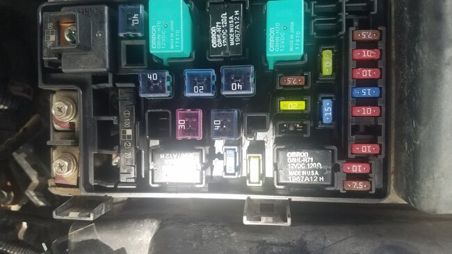

Jun 24, 2025 at 1:38 PM
Looks like Fuse 19 is missing; it feeds the Under-dash fuses 1-4. You can check for power on one of those pins for that fuse location, along with a possible short to ground on the opposite pin. I can't think of another reason why it would be missing. There seems to be quite a few electrical problems here. The low voltage of 8 volts in the video is still an issue.
Images (Click to enlarge)
Professional Diagram for 2CarPros Members
Click here to log in and view diagram.
Click here to log in and view diagram.
Professional Diagram for 2CarPros Members
Click here to log in and view diagram.
Click here to log in and view diagram.
Professional Diagram for 2CarPros Members
Click here to log in and view diagram.
Click here to log in and view diagram.
Professional Diagram for 2CarPros Members
Click here to log in and view diagram.
Click here to log in and view diagram.
Jun 24, 2025 at 3:32 PM
So I found the break in the wires in the overhead lamp circuit fixed it and replaced the 7.5 fuse. still no power making it to the lights and the key situation is still not bypassed and allowing the car to start. wondering where in the circuit I should look now to try to find the main source of the problem apparently.
Jul 1, 2025 at 12:25 PM
I assume the Map or doors lights are not working either? The Ceiling lamp is provided ground through the dash fuse box which is controlled by a solid state transistor, which is probably burned out. What fuses have full battery power in the dash fuse panel? And whats the situation with the missing fuse in the Under hood fuse box? That 40Amp? Did you check the pins where the fuse sits with a test light and see if theres power on one pin at least? And check the other pin for a short to ground.
Image (Click to enlarge)
Professional Diagram for 2CarPros Members
Click here to log in and view diagram.
Click here to log in and view diagram.
Jul 2, 2025 at 6:48 PM
Repair Safety Notice: This information is for general instructional purposes only. Vehicle repair can be dangerous. Verify all information, follow manufacturer service procedures, use proper tools and safety equipment, and consult a qualified repair shop when needed.