The only way you're going to get 12.5 volts at the starter terminal is when it's not cranking the engine. You can have 99 out of 100 strands of copper wire broken in that fat cable and you'll get 12.5 volts, but you know you won't get enough current through that one strand to crank the engine. That's why the only measurement that has any value is during cranking.
The high current drawn by the starter at first draws the battery voltage way down, perhaps to as low as five or six volts. After less than a second, when the starter gets up to speed, its internal parts are exactly the same as a generator, and in fact, when it's spinning, it develops a voltage that opposes the battery voltage. That means that while, lets say, 200 amps is leaving the battery, the starter develops an opposing current of, ... Oh, ... 50 amps. You can't measure that 50 amps, but you can measure the results of it with a professional load tester. You'll see only 150 amps leaving the battery. That 50 amps is the result of the opposing voltage, or "back emf", (electromotive force). It's why an electric motor that isn't shorted will cause a fuse to blow when it is tight or forced to stall.
In the starter motor application, it draws high current until it gets up to speed, then current flow goes down the faster the motor spins. That means if there's less than a perfect connection in the circuit, the motor will draw too little current to get up to speed, it won't generate enough reverse current to oppose battery current, so current actually goes up. Yup, current flow is too high and speed is too low. The high current results in a large "voltage drop" across the bad connection. Bad connections in high-current circuits like this have resistance that is excessive, but it's way too small to measure with an ohm meter. We CAN, however, measure the results of that resistance. That is in the form of voltage drop measurements.
There are ways to shortcut this process but it takes longer to explain those shortcuts. Instead, measure just one connection at a time. We're looking for a mechanical connection in the circuit where more than 0.2 volts is dropped while it's under load. That means the measurements must be taken while cranking the engine. To start, put the voltmeter on one of the lowest DC volts scales, typically the 2.0 volt scale. Put one meter probe on the battery's positive post, and the other probe on the cable clamp attached to that post. You'll see 0.00 volts because those two parts are the same point in the circuit. Now see what you get during cranking. Typically you'll find around 0.05 to 0.10 volts. If there is excessive resistance in that mechanical connection, you're going to see something obviously too high, like one to three volts.
You just tested the first mechanical connection. Do the same thing on the negative post and cable clamp. On the negative circuit, also measure between the engine block and the ground terminal bolted to it.
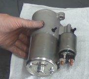
On the positive circuit, follow the battery cable to the next mechanical connection. As I recall, that cable bolts right onto the starter. Measure between that terminal end on the cable and the copper stud it's attached to.
We normally do not worry about the mechanical connection between the engine block and the transmission on cars where the starter is bolted to the transmission housing because that is a very beefy and solid connection. Also do not worry, at least right now, about the mechanical connection where the copper terminals are crimped onto the ends of the cables. You really can't get in there with the probes, but if there's corrosion and / or cut strands of wire, you'll see the excessive voltage drop on the first test. That one should have one meter probe on the battery's positive post, (not the cable clamp), and the other probe on the larger terminal on the starter, (not the terminal on the end of the cable).
Normally we would measure across two more mechanical connections in the positive circuit. Those are the two solenoid contacts. To include those in the measurement, you'd look for the second larger terminal on the solenoid and place the meter probe on the braided wire attached to it, (not the stud). I didn't bother with that because you have a new starter, so the solenoid contacts won't be an issue.
Be aware too that removing the starter to have it tested in a store is not a valid test. That's like saying you're strong enough to hold up a 100-pound sack of potatoes because you're holding up an empty bag. The only valid test is when the starter is under load trying to spin the engine. Getting back to that back EMF, a starter that is free-wheeling off the engine will spin at least twice as fast as normal, will develop a real lot of back emf, so it will only draw about 30 to 40 amps.
I won't go too deep into the next issue. Every starter motor has two somewhat independent circuits built in. There's two pair of brushes that each use a different part of the armature. That insures the motor will start spinning if one brush isn't making perfect contact. The concern is if one brush is totally open, you only have half a starter motor. It will draw exactly half of normal current, spin much too slowly, develop very little back EMF, and therefore draw very high current, which ends up being close to normal current. That means you will measure correct current flow, (around 150 amps), but the motor will spin very slowly. We don't have to worry about that since the starter has been replaced.
For my last comment of great value, if you cut the cable clamps off the battery cables and bolted on universal replacements, those are only meant to be temporary repairs. They were never meant to be a permanent fix. When you find those in the circuit you have to include them as another mechanical connection.
To finish my story on those mechanical connections and voltage drops during cranking, the most you're allowed at any one mechanical connection is 0.2 volts. More than that means take it apart, clean it, and tighten it. In addition, you're allowed a maximum of 0.4 volts in the entire circuit. You only have two mechanical connections in the negative circuit anyway. One is the cable clamp bolted to the battery's negative post and the other is the cable bolted to the engine block. Oops, you DO have a third one. That's the connection between the cable clamp and the cable bolted to it.
Technically, in the positive circuit, you have the cable clamp / battery post, the terminal bolted to the copper stud on the starter solenoid, the first internal solenoid contact, the second internal contact, and the braided wire bolted to the second large stud. Each one of those can have no more than 0.2 volts dropped across it, and all of them in total can have no more than 0.4 volts dropped across them during cranking. Most of the time those solenoid contacts and the braided wire cause so very few problems that we ignore them and only test down to the stud at the end of the battery cable.
There's one more observation you can make that might help. Turn on the head lights or watch the interior lights during cranking. If the starter is drawing excessive current, the lights will dim a lot. That's due to one more place where there is excessive resistance but we can't measure it. That's inside the battery. It is always going be a 12.6 volt battery. You see a much lower voltage at the posts during cranking because some of that voltage will be dropped across the battery's internal resistance in the plates and acid. If the lights do not dim very much during cranking, suspect a bad connection that is limiting the amount of current that can get through to the starter. Lower current flow means less voltage dropped inside the battery, more voltage at the posts, and less dimming of the lights during cranking.
Wednesday, December 30th, 2020 AT 5:51 PM
(Merged)


