Hello LESLIE PAYNE,
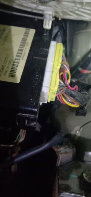
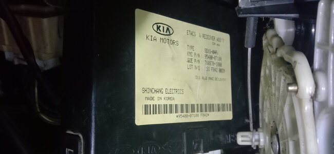
That is like a body control module. ETACS stands for Electronic Time and Alarm Control System. It will run things like wipers, door locks, courtesy lights etc. Unfortunately, it is not the PCM.
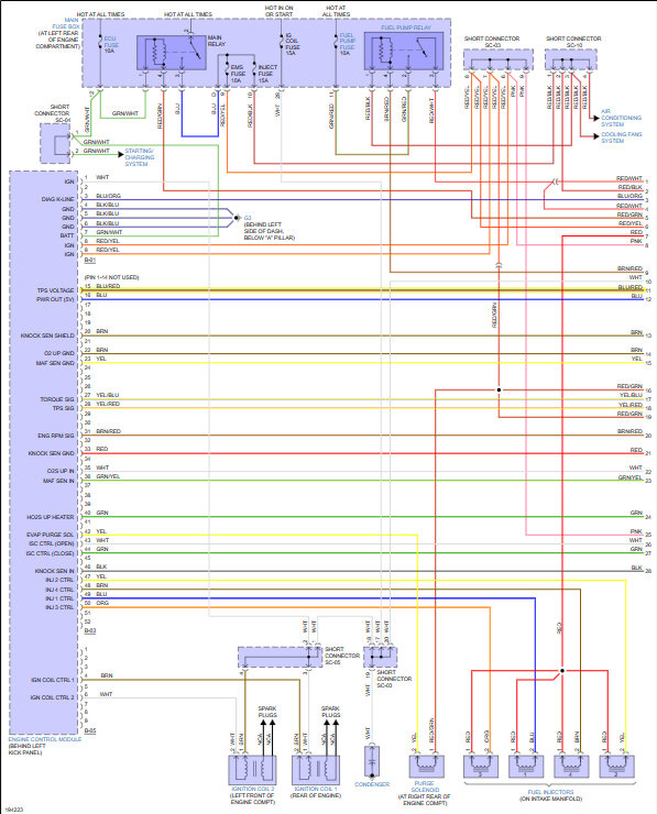
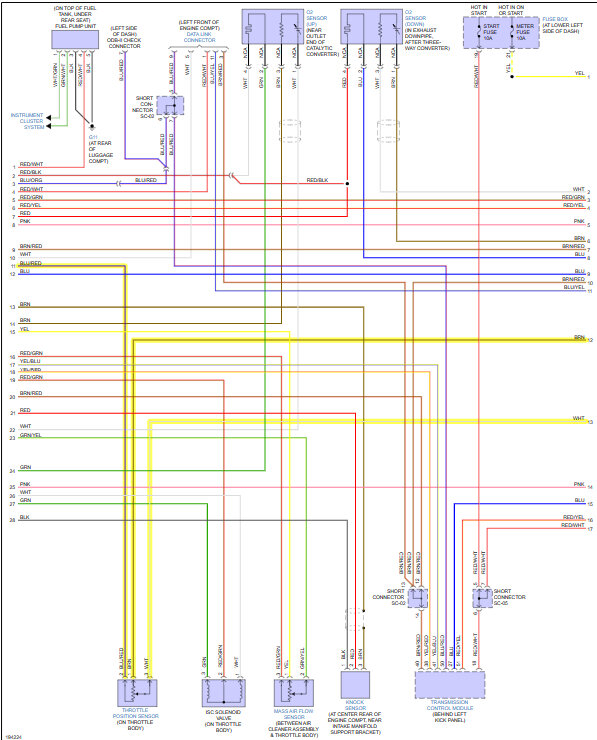
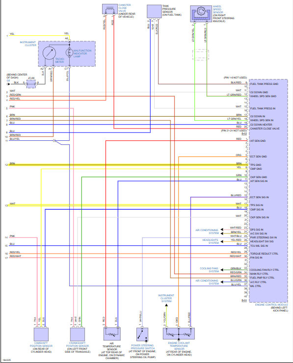
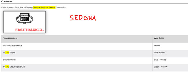
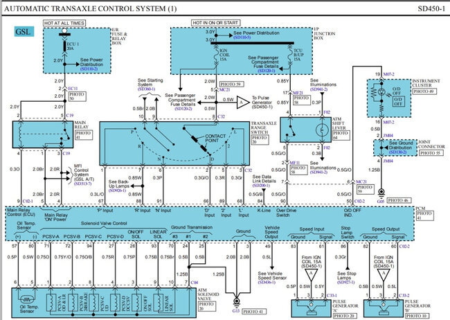
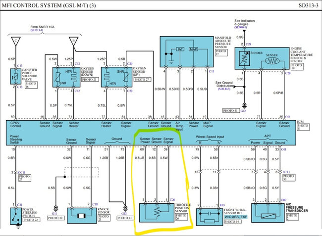
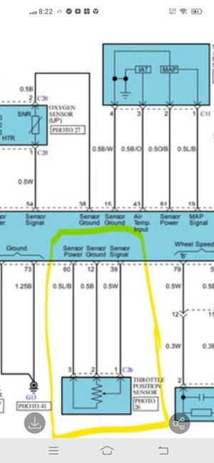
The numbers in the diagram are the terminal on the connector at the PCM. No, you will more than likely not see them on the connector.
Yes, you are correct, there is no yellow wire. But we don't need it because we know what the wires are from testing.
Yes, I am aware of what feet and inches are thank you for clarifying and yes, we are based in the United States. I wanted to know if it spliced back into the wire or it went off somewhere else, regardless of the length.
I found something that says normally on the KIA Picanto, the PCM is usually in the engine compartment. It can also be found sometimes on the passenger side under the dashboard or glove box.
Also, the guy from eBay I messaged finally answered me and said it's next to the engine. Not very helpful but looking more like it is in the engine compartment.
But let's pivot for a moment.
I think the 5 volts on the signal wire is normal because it is unplugged. The PCM is sending the voltage to detect a fault.
When unplugged, it is designed to place 5-volts on the signal wire to force a defective condition to be detected and set a fault code. Most engine management sensors are two-wire circuits that contain a 5-volt reference and a signal return wire or three-wire circuits that contain a 5-volt, signal return and auxiliary ground wire. So, if you disconnect the sensor, you should see 5-volts on the signal wire.
This is from multiple sources. It makes sense because once the sensor is plugged in, we are actually getting a reading from the sensor and the 5 volts disappears.
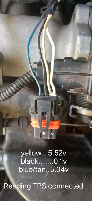
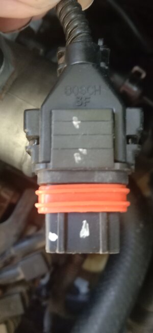
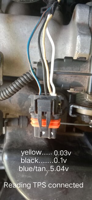
So, I think we need to plug the sensor back in. Then with the key on engine off, I want you to measure the voltage of the signal wire at the connector with it plugged in. Then measure the voltage past the repair on the wire. I want to see if the voltage is dropping. Ideally, I would like to check the whole wire but until the PCM is located, we will have to test as far down the wire as possible.
Allowable voltage drop on any connections on low-current circuits is 0.00v.
Because it has such a low voltage signal, the smallest crimp, connection etc. Can cause a drop in voltage. So, the end result is the PCM receives the lower voltage which tells it the throttle is in a different position than it is, based on the value it is receiving.
This can cause some of the issues you are experiencing.
Let me know what you get for readings.
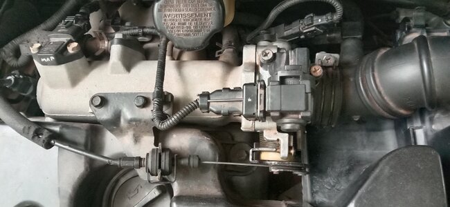
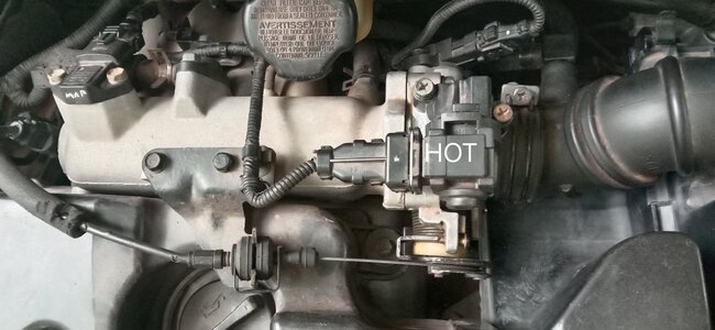
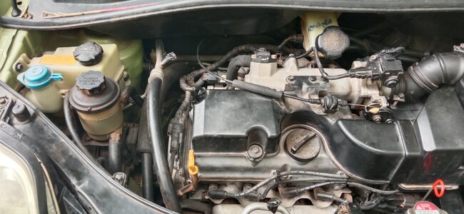
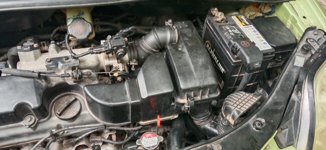
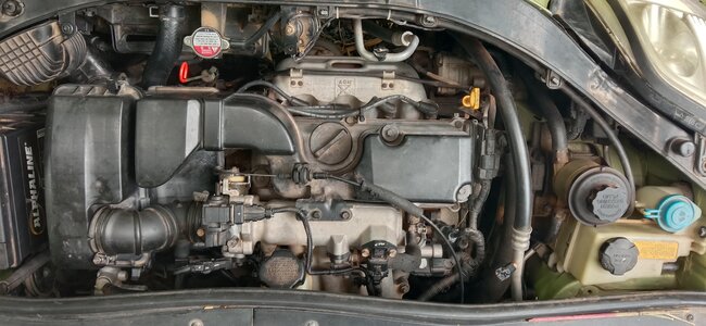
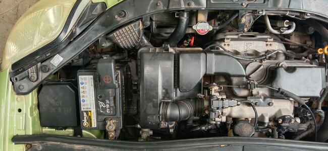
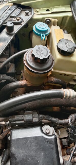
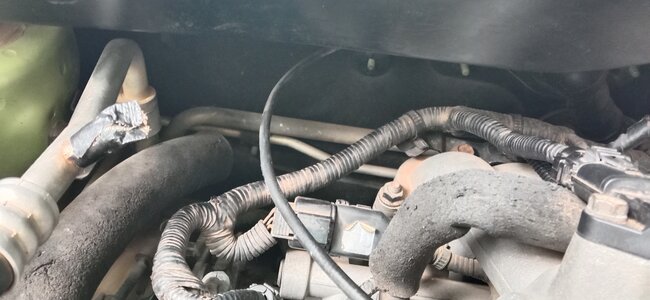
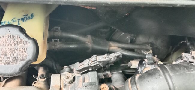
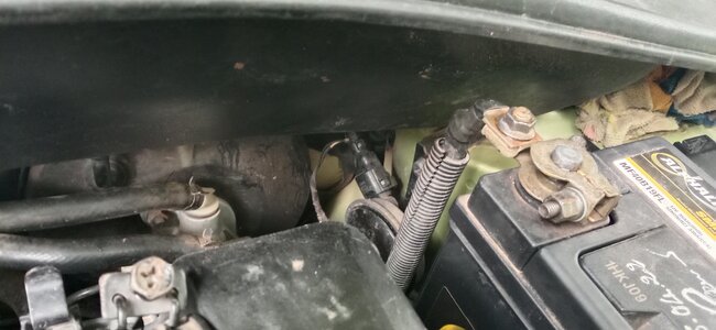
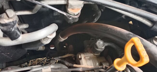
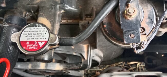
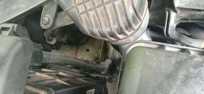
If you could also, please take some photos of the engine compartment for me so I can see where things are and maybe I can help identify the PCM. Since I have no information at all on this vehicle this will help me help you.
As far as the fans are concerned, Fan 1 is a regular cooling fan or low speed, Fan 2 is for when A/C is on or high speed.
What is going on with it? Is the vehicle overheating? Does it come on when you turn on the A/C?
Is the gauge on the dash working?
If there is a pocket of air by the sensor, possibly from low coolant, the PCM won't know the right temperature and it won't turn the fans on. It will also make it, so it won't run correctly because it doesn't think it is up to operating temperature.
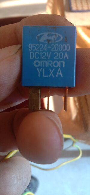
A bad relay could also cause the fans to not operate. You can try switching the 2 relays as long as they are exactly the same and see if the fan comes on.
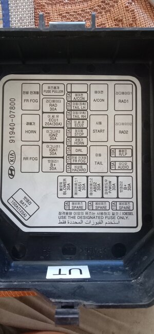
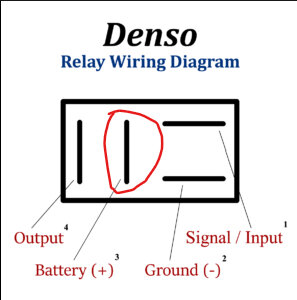
I have added a couple of images for you.
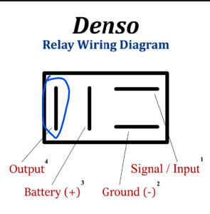
First check both relay cavities that are circled in red and see if they have power with the key off. If not turn the key on engine off and see if they have power, then. This is Terminal 87 and is usually 12v from the battery. It might be switched on power on your vehicle, looks like it is the case on the KIA Rio.
Next check the terminal circled in blue in both relay cavities and make sure it does not have power, it shouldn't. This should be Terminal 30 and it should go right to the fan.
You can use your multimeter and put it on ohms and take one lead to terminal 30 and the other to power side of fan. You should have low resistance but not O.L, yours may also beep when you make a connection.
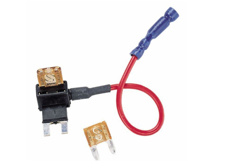
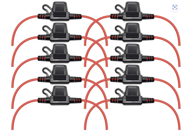
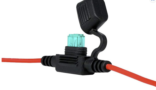
Then take a fused jumper, like mentioned earlier, and go from 87 to 30. This should turn on the fan. One relay may have to be installed to get power at another relay. So, start by checking with one of the relays still installed.
Let me know what you find and if you can get it running.
Thank you,
Brendon
Images (Click to make bigger)
Friday, July 14th, 2023 AT 4:46 PM
