***Start with this test***
SPARK TEST
1. Disconnect spark plug wires. Remove spark plugs. Install spark plug on each spark plug wire. Ground spark plug against cylinder block.
2. Crank engine and check for spark. If spark does exist, check ignition coil, ignitor and distributor
electrical connections.
3. If electrical connections are okay, go to next step. If electrical connections are defective, repair as
necessary and recheck for spark.
4. Using ohmmeter, check resistance of spark plug and ignition coil high tension wires. Resistance should be within specification. Maximum Ohms 25,000 Per Wire. If resistance is within specification, go to next step. If resistance is not within specification, replace high tension wire.
5. Turn ignition on. Check for battery voltage at ignitor and ignition coil positive terminal. If battery
voltage exists, go to next step. If battery voltage does not exist, check wiring between ignition switch, ignition coil and ignitor.
6. Check ignition coil resistance. Cold: Primary @.36-.S55, Secondary 9000-15,400 ohms. Hot: Primary.45-.65, Secondary 11,400-18,100 ohms. If ignition coil resistance is within specification, go to next step. If ignition coil resistance is not within specification, replace ignition coil.
7. Check pick-up coil resistance. Cold: Pick-Up Coil Terminals G+ & G-, 185-275 ohms. Hot: Pick-Up Coil G+ & G-, 240-325 ohms. If pick-up coil resistance is within specification, go to next step. If pick-up coil resistance is not within specification, replace distributor assembly.
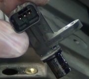
8. Check resistance of crankshaft position sensor. Cold: 1630-2740 ohms, Hot: 2065-3225 ohms. If
crankshaft position sensor resistance is within specification, go to next step. If crankshaft position
sensor resistance is not within specification, replace crankshaft position sensor.
9. Check pick-up coil air gap. Spec.008-.016 (inches). If pick-up coil air gap is correct, go to next step. If pick-up coil air gap is incorrect, replace distributor assembly.
10. Check ignition IGT signal from Engine Control Module (ECM). If ignition IGT signal from ECM
is defective, a diagnostic trouble code P1300 will be set in the ECM memory to indicate a ignitor
circuit malfunction.
11. If IGT signal is okay, substitute another ignitor and recheck system operation. If IGT signal is defective, check wiring between Engine Control Module (ECM), distributor and ignitor. If wiring is defective, repair wiring as necessary and recheck system operation. If wiring is okay, substitute another ECM and recheck system operation.
CRANKSHAFT POSITION SENSOR RESISTANCE
1. Crankshaft position sensor is located on front (timing belt end) of engine, just behind the
crankshaft pulley. Disconnect electrical connector for crankshaft position sensor, located near oil dipstick.
2. Using ohmmeter, check resistance between terminals on crankshaft position sensor. Replace
crankshaft position sensor if resistance is not within specification. Reinstall electrical connector.
IGNITION COIL RESISTANCE (DISTRIBUTOR TYPE IGNITION SYSTEM)
1. Disconnect wiring from ignition coil so ignition coil is isolated from the system. Using an ohmmeter, check ignition coil primary resistance between ignition coil positive (+) and negative (-) terminals.
2. Check ignition coil secondary resistance between ignition coil positive (+) terminal and high tension terminal (coil wire tower). Replace ignition coil if resistance is not within specification.
PICK-UP COIL RESISTANCE
1. Disconnect electrical connector on distributor and note pick-up coil terminal identification on the
distributor.
2. Using ohmmeter, check resistance between specified terminals. Replace distributor assembly if pick-up coil resistance is not within specification. Reinstall electrical connector.
PICK-UP COIL AIR GAP
1. Remove distributor cap. Using non-magnetic feeler gauge, check pick-up coil air gap between signal rotor and pick-up coil projection.
2. Replace distributor assembly if pick-up coil air gap is not within specifications.
Wednesday, October 14th, 2020 AT 1:14 PM
(Merged)


