Visually inspect engine compartment to ensure that all vacuum hoses and spark plug wires are properly routed and securely connected. Examine all wiring harnesses and connectors for insulation damage, burnt or overheated wires, and loose or broken terminals.
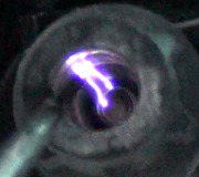
Ensure that battery is fully charged and that all accessories are off. Check that TFI ignition module is securely fastened to distributor base. Obtain Spark Tester (D81P-6666-A). See Fig 1. A spark plug with a broken side electrode is NOT recommended as it may lead to incorrect results.
When inspecting wiring harness, both a visual inspection and a continuity check should be performed. When checking continuity perform a "WIGGLE" test to assist in finding intermittent faults.
TESTING > PRELIMINARY STEPS > Crank Mode
Connect Spark Tester (D81P-6666-A) between ignition coil wire and engine ground. Crank engine while checking for spark at tester. If spark occurs, inspect distributor cap and rotor for damage or carbon tracking.
If no spark occurs, remove distributor cap and crank engine to ensure distributor shaft rotates. If distributor shaft does not rotate while cranking engine, repair as necessary. If distributor rotates go to STATOR test.
TESTING > PRELIMINARY STEPS > Run Mode
Place transmission in Park or Neutral and set parking brake. Disconnect wire at "S" terminal of starter relay and attach remote starter switch.
Connect Spark Tester (D81P-6666-A) between ignition coil wire and engine ground. Turn ignition switch to "RUN" position. Using remote starter switch, crank engine while watching for spark at tester. If spark is present, ignition system is okay. If spark was not present, go to next test.
TESTING > TFI CONNECTOR VOLTAGE CHECK
Disconnect wiring harness connector from TFI module. Inspect connector for dirt, corrosion, or damage. Repair if necessary. Disconnect wire at "S" terminal of starter solenoid.
Attach negative voltmeter lead to distributor base. Measure voltage at battery. With negative lead of voltmeter still connected to distributor base, check voltages at TFI ignition module wiring harness terminals. See WIRING HARNESS TEST table. See Fig 1.
If all readings are at least 90% of battery voltage, replace TFI module. If any reading is less than 90% of battery voltage, inspect wiring harness and connectors. Also check for a worn or damaged ignition switch. Repair or replace as necessary.
WIRING HARNESS TEST
Connector Terminal No. Wire (Circuit) Ignition Switch Test Position
3 Run "RUN" or "START"
4 Start "START"
Fig 1: TFI Wiring Harness Connector
TESTING > IGNITION COIL & SECONDARY COIL WIRE
Substitute coil and coil wire with known good parts. Install Spark Tester (D81P-6666-A) between ignition coil wire and engine ground. Crank engine. Turn ignition off. If spark is present, determine if coil and/or secondary wire was cause of no spark,
replace part(s) as necessary.
TESTING > WIRING > All Others
Disconnect in-line connector near TFI module. Install Spark Tester (D81P-6666-A) between ignition coil wire and engine ground. Crank engine. Turn ignition off. If spark was present, check PIP and ignition ground wires for continuity. Service wiring as necessary. If wires are okay, see appropriate EEC-IV article in COMPUTERIZED ENGINE CONTROL section listed below. If spark was not present, go to IGNITION COIL SUPPLY VOLTAGE test.
Image (Click to make bigger)
Saturday, February 28th, 2015 AT 6:57 PM


