Oxygen sensor replacement

1995 TOYOTA AVALON
200,000 MILES • 3.0L • V6 • 2WD • AUTOMATIC
Avatar
AVALON1995
  • MEMBER
  • 121 POSTS
Can you please provide the procedure on how to replace the oxygen sensor on Bank 1 Sensor 2, the one after the catalytic converter? By any chance, does the passenger car seat have to be removed?


Thank you!


Cheers!
Nov 18, 2020 at 7:03 AM
Advertisement
Avatar
JACOBANDNICKOLAS
  • Experienced Mechanic
  • 110,240 POSTS
Hi,

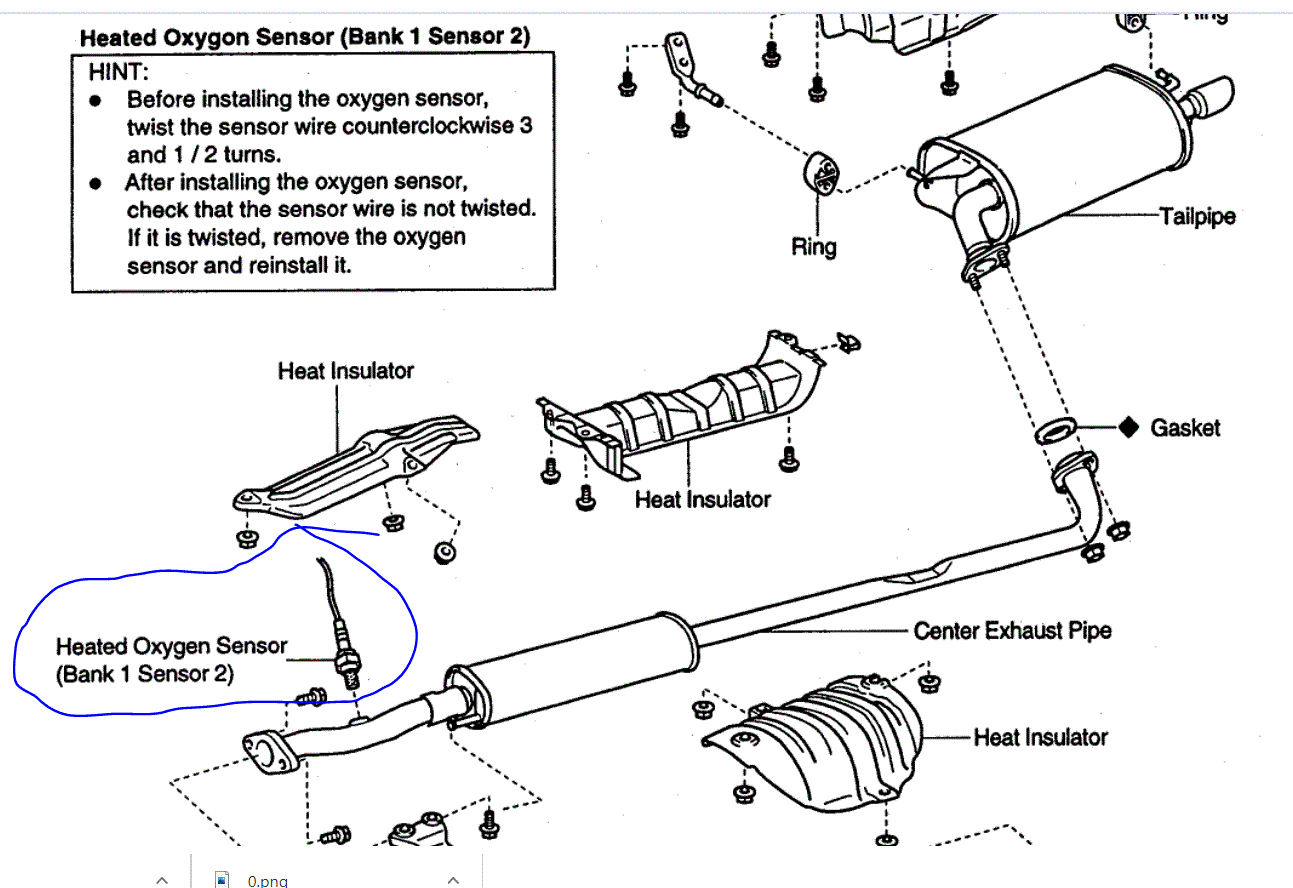
The oxygen sensor is mounted on the exhaust system and on the exterior of the vehicle. It is located after the catalytic converter and before the resonator. See pic 1 for location.

Now, because there is a wire attached to it, you can't use a standard socket for removal. You have two choices. First, try to remove it with an open-end wrench. In all honesty, they are usually rusted in place and that type of a wrench usually will round off the hex, so don't allow that to happen if it seems too tight.

Second, you need to get a socket designed for the removal and install of an O2 sensor. It will be open on the side allowing the wire to be routed out of the socket. That is the best choice of tools.

You don't need to remove the seat. Also, when looking at the attached pic, make sure to read the text in the box.

Also, here is a link that explains in general how an O2 sensor is replaced. I thought it may be helpful for you.

https://www.2carpros.com/articles/how-to-replace-an-oxygen-sensor


Let me know if this helps or if you have other questions.

Take care,
Joe
Apr 6, 2021 at 4:58 AM
Avatar
I-SMOGEM
  • Experienced Mechanic
  • 118 POSTS
After hours of searching for an answer to your question, the best I could come up with is for a 1997. Honestly, I don't know if the 1995 is the same.

https://www.youtube.com/watch?v=-ivgya9rOLo

Hope this helps... Glenn
Apr 6, 2021 at 4:58 AM
Avatar
AVALON1995
  • MEMBER
  • 121 POSTS
My understanding is that the wiring harness for the downstream O2 sensor is located inside the car under the front passenger seat. I have replaced the upstream O2 sensors in the past, so thankfully I'm familiar with how to do it. However, the downstream O2 sensor is more challenging. I couldn't find a video on YouTube for my car model, so the next best thing I found was for a 2001 Toyota Avalon. Are you sure that the car seat doesn't need to be removed? According to the video, it involves removing the front passenger car seat and the carpeting. Hence, I'm trying to find out if the procedure is the same for my car, a 1995 Toyota Avalon. I have attached the video link. Please let me know if it can be applied to my car or if it's a different procedure.


https://youtu.be/6fii05FVoNw

Thank you!

Cheers!
Apr 6, 2021 at 4:58 AM
Avatar
JACOBANDNICKOLAS
  • Experienced Mechanic
  • 110,240 POSTS
Hi,

Now that I watched the video, I do remember the wiring going under the seat. The best way to determine if your model year is the same is by checking if the wiring goes up into the floor of the vehicle. Have you checked that yet? If it does, then the seat and carpet will need to be moved.

Joe
Apr 6, 2021 at 4:58 AM
Avatar
AVALON1995
  • MEMBER
  • 121 POSTS
I have gone on the underside of my car and have seen that the wiring does indeed go up into the floor. I guess that video is going to come in very handy.

Btw, how can I even determine if the downstream O2 sensor needs to be replaced for sure? I don't have a check engine light on. The live data on my scan tool indicates that the voltage for my upstream 02 sensors fluctuate just as they are supposed to. However, my downstream O2 sensor (Bank 1 Sensor 2),which is highlighted in blue in the attached video, remains flat at zero (0.000) both at idle and with the RPM raised above 2500. So what does that tell us? Does it mean that the O2 sensor is faulty? Is it even possible that the O2 sensor could be faulty, but not necessarily trigger a check engine light?

Thank you!

Cheers!
Apr 6, 2021 at 4:59 AM
Avatar
AVALON1995
  • MEMBER
  • 121 POSTS
Were you able to look into my question from my very last post?


Thank you!

Cheers!
Apr 6, 2021 at 4:59 AM
Avatar
JACOBANDNICKOLAS
  • Experienced Mechanic
  • 110,240 POSTS
Hi,

Chances are, if the sensor is connected and the connection isn't damaged or corroded, the sensor is bad. You can check the resistance of the sensor itself.

If you check resistance, you should have between 11 - 16 ohms at 20°C.

Can you tell me what the code is you are getting?

Joe
Apr 6, 2021 at 4:59 AM
Avatar
AVALON1995
  • MEMBER
  • 121 POSTS
Like I mentioned in my previous post, there is no code, in fact, there is no check engine light on. The Live Data on my scan tool indicates that the voltage for the downstream O2 sensor is zero. Have you seen the very brief video I had attached in my previous post?

Apr 6, 2021 at 4:59 AM
Avatar
JACOBANDNICKOLAS
  • Experienced Mechanic
  • 110,240 POSTS
Hi,

I did see it. The only thing you can do is visually inspect the wiring and connector. If that all appears good, check the resistance in the sensor. If the resistance is within spec, then we will have to start checking wiring and connections up from the sensor.

Joe
Apr 6, 2021 at 4:59 AM
Avatar
AVALON1995
  • MEMBER
  • 121 POSTS
Checking the resistance will be my next step.
Apr 6, 2021 at 4:59 AM
Avatar
JACOBANDNICKOLAS
  • Experienced Mechanic
  • 110,240 POSTS
Sounds like a plan. Let me know what you find.

Joe
Apr 6, 2021 at 4:59 AM
Avatar
AVALON1995
  • MEMBER
  • 121 POSTS
I tried to trace the wiring, but it's really not accessible. I wish I would have taken pictures or recorded it to show you what I mean. I think the center console would need to be dismantled or something to trace the wiring. Do you have the procedure and the diagram that illustrates how to trace the wiring?
Apr 6, 2021 at 4:59 AM
Avatar
JACOBANDNICKOLAS
  • Experienced Mechanic
  • 110,240 POSTS
Hi,

When I trace wires, I have to follow a wiring schematic. They don't specifically tell you where the wire runs through the vehicle. However, it shows where the wires go to.

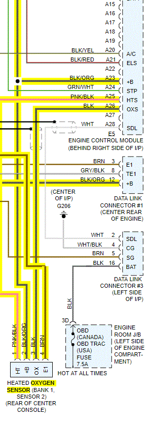
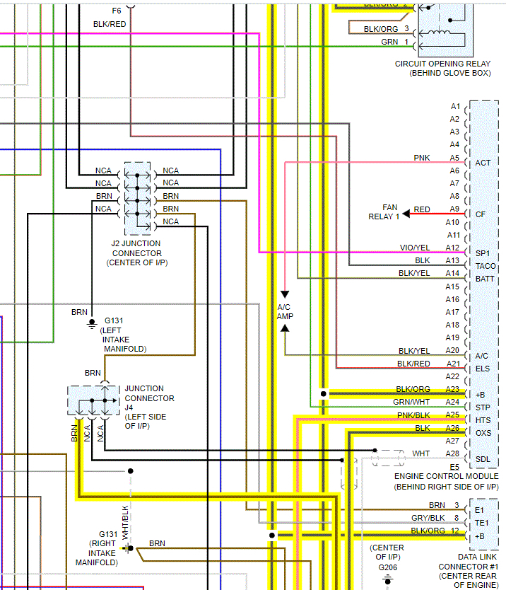
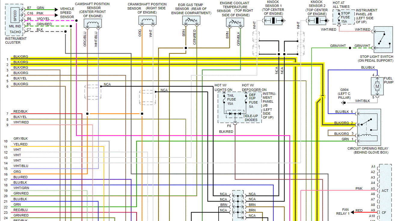
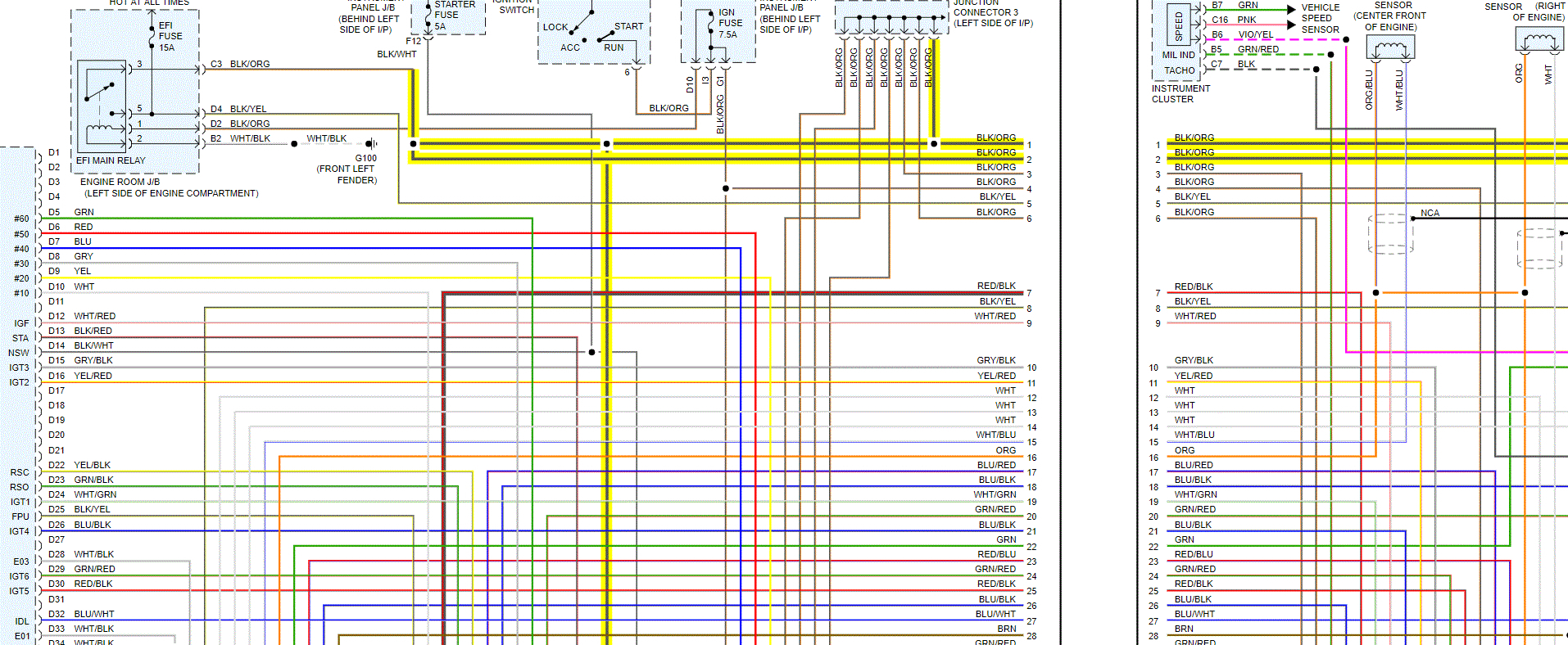
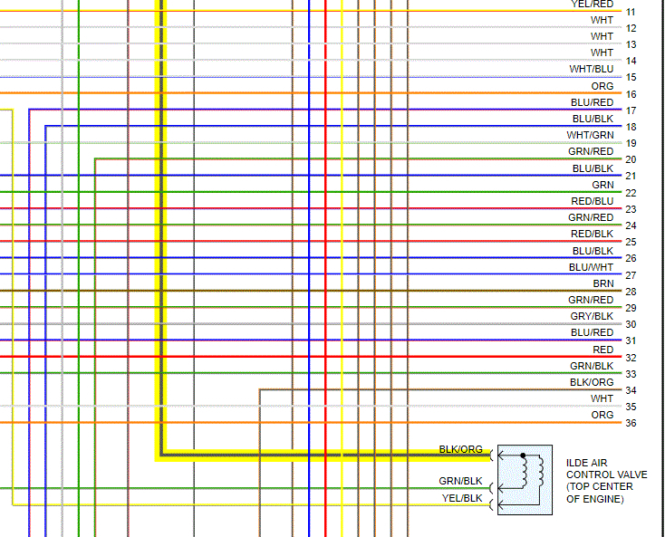
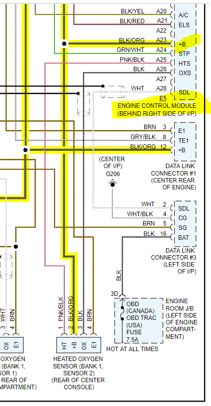
I attached several pics below. I started at the O2 sensor in question. I highlighted the wires from the sensor and traced them throughout the schematics so you can see where each wire goes. I don't know if it helps, but take a look through it and see if it helps you find the locations where the wiring goes. The pics are in order. If you could picture them laid out, one on top of the other, that is what I had.

I hope it helps.

Let me know.

Joe
Apr 6, 2021 at 4:59 AM
Avatar
AVALON1995
  • MEMBER
  • 121 POSTS
Just so that I understand, is the purpose of tracing the wiring is to conduct a continuity test or is there something else? As far as this car is concerned, there is no functioning downstream O2 sensor. Hence, what would be the downside of driving this car without a downstream O2 sensor?

Please let me know if I have this correct. From what I can figure out looking at the schematics, #1 (pink/black) and #3 (black) wires are connected to the ECM. The #4 (brown) wire is connected to the Junction Connector, where in the world is that? Is there a diagram that shows its location? Now, when it comes to the #2 (black/orange) wire, it's very confusing, because it seems like it's connected at several spots. Can you please explain what the deal is with that wire? Where is it connected to in reference to the downstream O2 sensor.

Thank you!

Cheers!
Apr 6, 2021 at 4:59 AM
Avatar
JACOBANDNICKOLAS
  • Experienced Mechanic
  • 110,240 POSTS
The brown wire is connected to those things under the instrument panel (see pics). The black/orange does jump. It branches from the circuit relay.

My manual doesn't show exact locations. Just general ones.

I hope you understand. As far as driving without that sensor, the car will run fine, but you may notice a decrease in fuel mileage. That is how the computer determines the air-fuel ratio that is needed.
Apr 6, 2021 at 4:59 AM
Avatar
AVALON1995
  • MEMBER
  • 121 POSTS
The purpose of tracing the wiring, is it solely to conduct a continuity test or is there something else?

I'm curious to find out why a check engine light has not been triggered with the downstream O2 sensor or the wiring not functioning?


Apr 6, 2021 at 4:59 AM
Avatar
JACOBANDNICKOLAS
  • Experienced Mechanic
  • 110,240 POSTS
Since you are getting nothing when testing at the sensor and the sensor is good, I suspect the wire is damaged at some point or at the PCM. As far as the light not turning on, there could be an issue with the PCM. We will need to work back to it and if there is still nothing found with the wiring, then we will need to check at the PCM itself.

Joe
Apr 6, 2021 at 4:59 AM
Avatar
AVALON1995
  • MEMBER
  • 121 POSTS
From what I understand, the voltage for the upstream oxygen sensors is supposed to fluctuate between 0.1 - 0.9. For the downstream oxygen sensor, my understanding is that the voltage is supposed to be steady, however, what kind of voltage should I see? At one point, for the voltage, I saw a reading of 0.020, 0.015, and 0.010 briefly. What does that mean?


I conducted a continuity test for the downstream wiring that are connected to the PCM and they all passed. What should be my next step?

Thank you!

Cheers!


Apr 6, 2021 at 4:59 AM
Avatar
JACOBANDNICKOLAS
  • Experienced Mechanic
  • 110,240 POSTS
Hi,

There should be a 5 volt reference to the sensor. The ohms should be between 11 and 16 ohms.

Joe
Apr 6, 2021 at 4:59 AM
Avatar
AVALON1995
  • MEMBER
  • 121 POSTS
Is it supposed to be 5 volts or 0.5 volts?

As I mentioned, the continuity test passed and the resistance was within spec. So, at this point, what else should I do to rectify the issue?
Apr 6, 2021 at 4:59 AM
Avatar
JACOBANDNICKOLAS
  • Experienced Mechanic
  • 110,240 POSTS
Hi,

Since this is sensor 2, it should remain somewhat steady around .5 volts.

If that isn't close to what you see, go back to the ECM to see if it is different.

Joe
Apr 6, 2021 at 4:59 AM
Avatar
AVALON1995
  • MEMBER
  • 121 POSTS
Hi,
I'm not sure I understand what you would like me to check at the ECM. I''ve already conducted a continuity test on the downstream O2 wires that are connected to the ECM and they all passed. What else is there to be done at the ECM?


Thank you!

Cheers!
Apr 6, 2021 at 4:59 AM
Avatar
JACOBANDNICKOLAS
  • Experienced Mechanic
  • 110,240 POSTS
What was the voltage readings you were getting at the sensor? If it is within in range and you are still getting a code and the ground is good, then there is likely an issue with the ECM. If the voltage wasn't within spec, then we need to check voltage at the ECM.

If the sensor is good, the wiring is good, the voltages are good, and you still get a code, then the problem is likely in the ECM.

If the voltages are not within spec, then we need to check the voltage at the ECM.

Let me know.
Joe
Apr 6, 2021 at 4:59 AM
Avatar
AVALON1995
  • MEMBER
  • 121 POSTS
Let me recap some things for you, since it looks like you may have forgotten the details.

There is no code whatsoever and there is no check engine light either. The live data on my scan tool indicates that my upstream oxygen sensors are in good operation as their voltage fluctuate between 0.1- 0.9. However, for my downstream oxygen sensor, the voltage remains flat at 0.000 and that is where the issue is. At one point on a different day, the voltage reading was briefly at 0.015, but almost all the time, it remains flat at 0.000. I have attached the video for your reference again.

The resistance for the downstream oxygen sensor falls within spec and the continuity test for the wires that are connected from the wiring harness to the ECM have passed.

So, at this point, what else can I do to troubleshoot why the downstream oxygen sensor shows no voltage? Would replacing the oxygen sensor resolve the issue despite the resistance falling within spec?

Thank you!

Cheers!
Apr 6, 2021 at 4:59 AM
Avatar
KASEKENNY
  • Experienced Mechanic
  • 18,907 POSTS
If I can just jump in and offer my observation. If your downstream sensor is not reading a voltage on your scan tool then I suspect Joe is correct that you have an issue with the ECM if the wiring checks out as you stated.

When you are monitoring information on the scan tool then you are basically just viewing what the module is seeing from the sensors. So if you are getting 0 volts on the downstream sensor according to the scan tool then you either have a wiring, sensor, or module issue. You said the sensor and wiring check out. This leaves the module.

So when you checked the wiring, can you give the detail about how you checked it? I assume you check resistance but how did you do it and what were the measurements for each wire? Did you unhook the connectors at the ECM and sensor or did you back probe? This is important because if you prove out the wiring is ok and the sensor is not the issue then you have either a connection issue (rare) with one of the terminals at the sensor or ECM, or a module issue.

The way to check this is to do as Joe stated, what are these same voltages at the ECM using a meter. Just connect everything up and then back probe the ECM connector. If you have proper voltage at the ECM on your meter then you know the ECM is not accurate or that terminal at the ECM is not making contact with the ECM terminal. However, if this is the case, I suspect when you back probe it, you will get intermittent contact or it start registering. So I always leave my scan tool hooked up and monitor what the module is seeing and what you are seeing on the meter.

If the meter says proper voltage at the ECM and the ECM doesn't then the ECM is the issue. However, if it starts working while you have it back probed or you see the voltage jumping around while you are moving the back probe then you have a connection issue at the ECM connector.

Hopefully that helped. Thanks
Apr 6, 2021 at 4:59 AM
Join 2CarPros for free, one of the most advanced car repair communities on the internet. From first-time drivers to seasoned mechanics, everyone is welcome to reply, share details, and get better answers. You can add a temporary image or video first; uploads are limited to 20 MB.
Ask a Free Question
Repair Safety Notice: This information is for general instructional purposes only. Vehicle repair can be dangerous. Verify all information, follow manufacturer service procedures, use proper tools and safety equipment, and consult a qualified repair shop when needed.