

Sep 24, 2026 at 1:46 PM
No crank no start U0100 Code?
12 volts with key on on blue pin 3
Did not get 5 volt on what/ black wire pin with key on
Sep 24, 2026 at 2:04 PM
Pin 43 and 44 tan n black and tan read 128 Ohms
Sep 24, 2026 at 2:14 PM
Pin 43 and 44 I have 128 ohms
Sep 24, 2026 at 5:20 PM
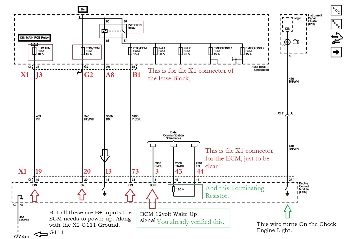
Since you are getting the Wake Up signal, a good resistance reading of 120 Ohms on the terminating resistor threw pins 43 & 44, thats good. I know you are not getting power on the Pink/Black wire, but that gets power from the PWRTRN relay up top on the diagram and since the ECM is most likely not grounding the Brown wire (pin 13) or that wire is broken in between the ECM and fuse/relay box, the relay will not be grounded. Take a look a the under side of the fuse boxes too, sometimes you can spot a broken wire, especially in the engine compartment where corrosion in the wiring harness is common.
Look carefully at the harness if you are missing power or ground.
https://2carpros.com/articles/how-to-check-an-electrical-relay-and-wiring-control-circuit/
https://2carpros.com/articles/how-to-check-wiring/
Look carefully at the harness if you are missing power or ground.
https://2carpros.com/articles/how-to-check-an-electrical-relay-and-wiring-control-circuit/
https://2carpros.com/articles/how-to-check-wiring/
Image (Click to enlarge)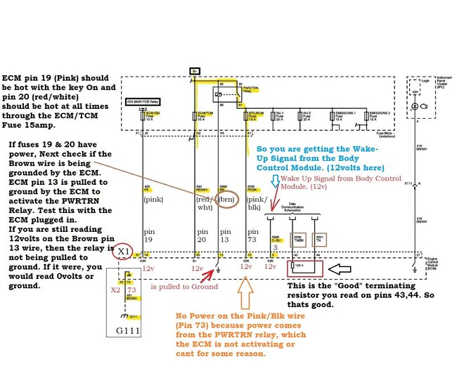
Sep 25, 2026 at 2:32 AM
Pink wire was 12 volt with key on and
Red and white wire was hot 12 volt with key off
Red and white wire was hot 12 volt with key off
Sep 25, 2026 at 4:50 AM
From ground to brown wire i got no volts
Sep 25, 2026 at 8:18 AM
Pin 13 0 volts
Brown wire
Brown wire
Sep 25, 2026 at 8:19 AM
Lets start over, please go over this video.
https://www.youtube.com/watch?v=6YRW8fyNudY&t
https://www.youtube.com/watch?v=6YRW8fyNudY&t
Sep 27, 2026 at 7:50 PM
That video is basic info witch I already did
Sep 29, 2026 at 3:08 PM
Ok so far the Pink wire is correct, it should have 12v from the Ignition switch. The Red/White should have 12v at all times, so that is correct.
The Brown wire is going to be Grounded by the ECM to close the PWRTRN Relay up top of the diagram. So if you put a test light hooked to B+ and touch the Brown wire (and try this with the key On and Cranking if it will. The Test light should find a path to ground throught the ECM.
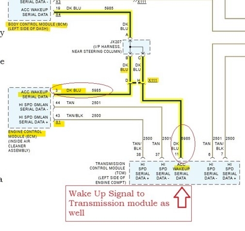
And lastly the DarkBlue wire from the Body Control Module should have 12v with the key On. Its Pin #3 at the ECM. That 12v has to be there or the ECM wont wake up.
Sep 30, 2026 at 7:46 AM
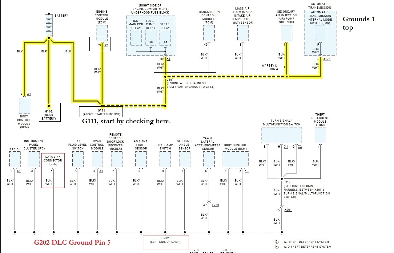
And check the Ground G111, its the only ECM ground. Connector X2 pin 73, its a Black/White wire.
Sep 30, 2026 at 7:47 AM
Ground G111 pin 73 ground is good black and white wire is good ground with test light
Sep 30, 2026 at 7:53 AM
So u want me to test pink and black with 73 and pin 3 bark blue wire with test light
Sep 30, 2026 at 7:57 AM
can i ran a ground wire to pin 13 , to give it a ground ?
Sep 30, 2026 at 12:24 PM
On test the DLC cam buss
Pin 4.16 I got 12 volts
5.16 12 volts .
.................
6. 14 60 ohms
..................
6.14 029 volts with key on
..........
1 . 16 I got 1.25 volts
Pin 4.16 I got 12 volts
5.16 12 volts .
.................
6. 14 60 ohms
..................
6.14 029 volts with key on
..........
1 . 16 I got 1.25 volts
Oct 1, 2026 at 8:21 AM
I did not get a ground on pin 86 of ecm relay with key on and test light to battery +
Oct 1, 2026 at 9:12 AM
Yes I know that, the ECM itself grounds that wire. On pins 4 and 5 you should have Ground not reading 12volts. It sounds like you have a bad ground. You are reading voltage drop on the negative side of the system, which is currently the entire system, hence the 12volts. That also explains why you are only reading 1.25volts on Pin 16 which is the power feed pin.
Image (Click to enlarge)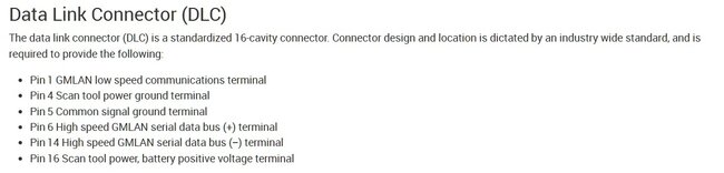

Oct 2, 2026 at 11:09 AM
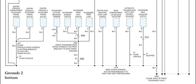
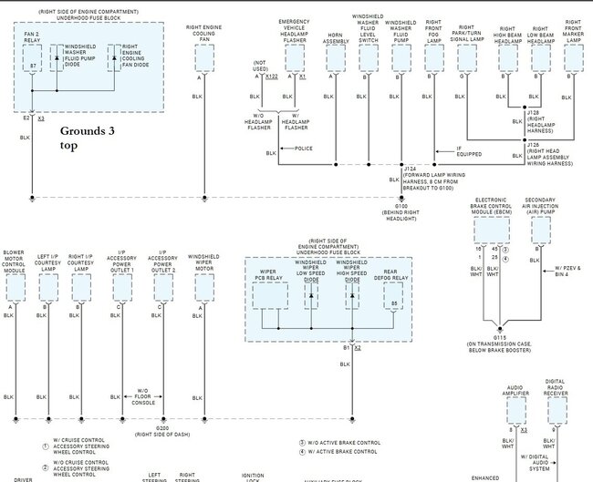
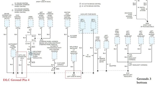
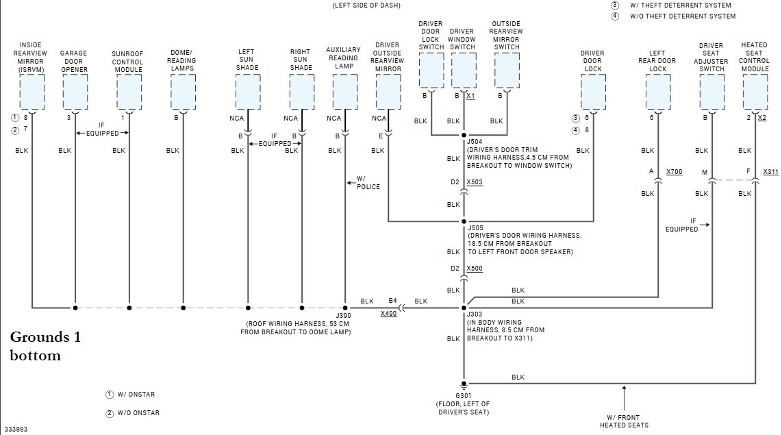
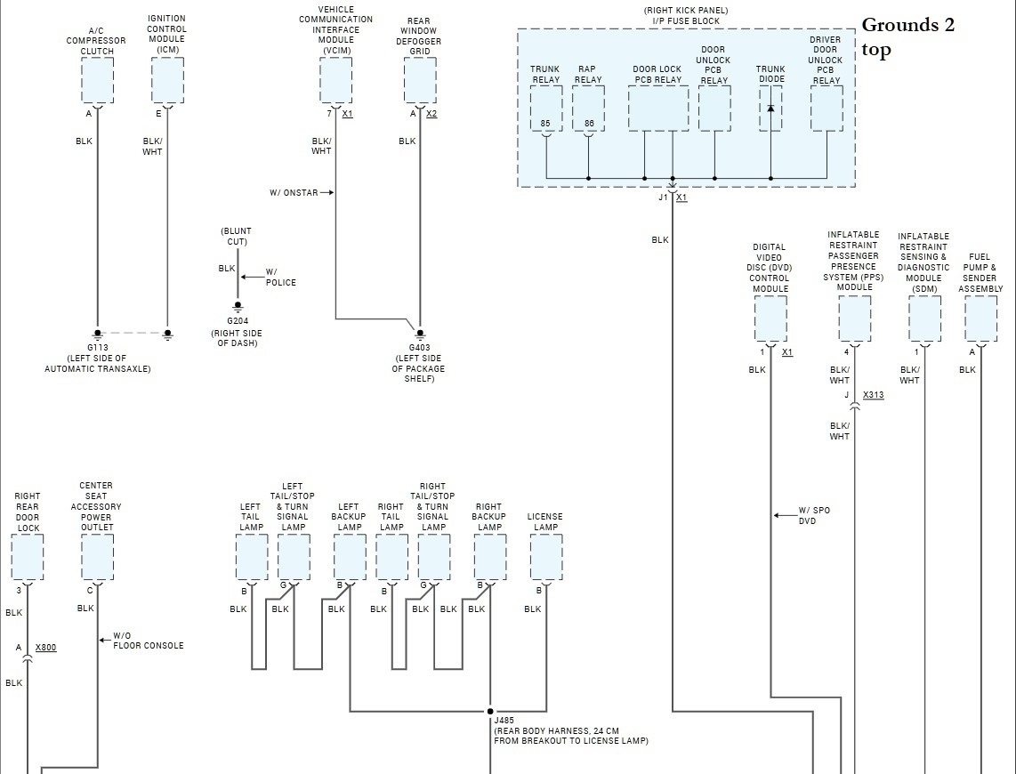
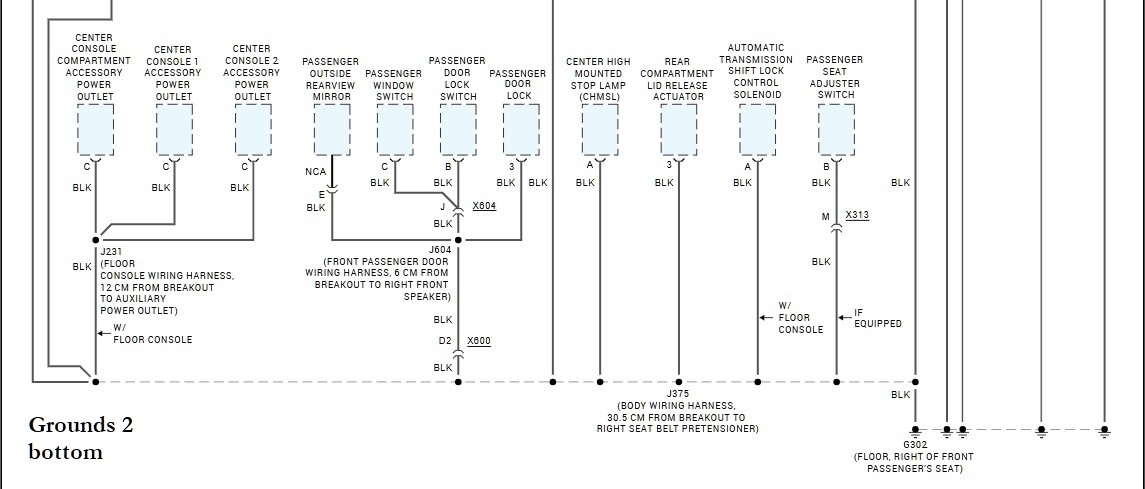
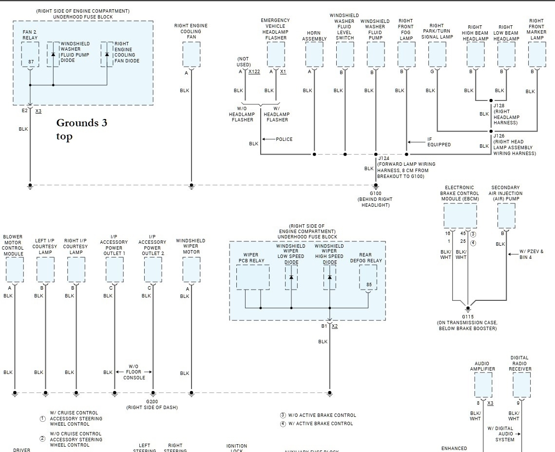
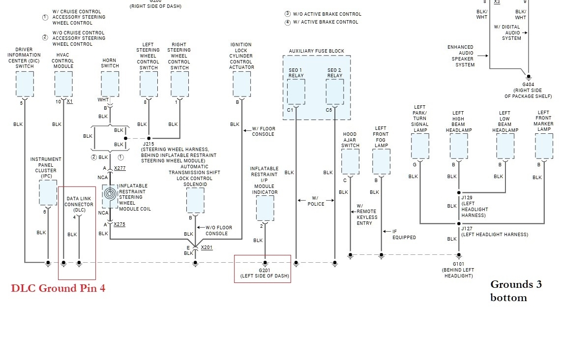
Here are the Ground wiring diagrams. Since you are getting "bad ground" readings everywhere, (ie, the low voltage readings where there should be a full 12volts). And the reading of 12volts on the ground pins at the DLC 4&5 means there is an open circuit between the DLC ground pins and the battery negative.
Images (Click to enlarge)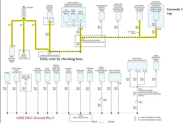
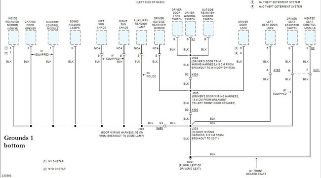
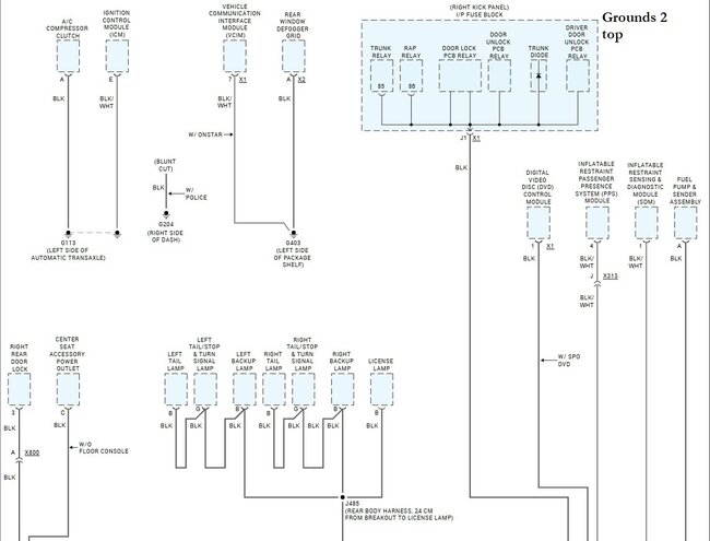
Oct 2, 2026 at 11:30 AM
I read 12 volts on pin 16 dlc
Oct 2, 2026 at 12:10 PM
And from 4 and 5 witch is ground and ground to 16 witch it positive I get 12 volt
Oct 2, 2026 at 12:11 PM
16 to 4 I got 60 ohms
Oct 2, 2026 at 12:15 PM
I read 0 volt from pin 4 to pin 5
Oct 2, 2026 at 5:21 PM
I not tryin to confused u " I got 12 volts on pin 16 of the DLC
Oct 2, 2026 at 5:23 PM
It's pin 6 to pin 14 60 I read 60 ohms
Oct 2, 2026 at 5:24 PM
If there is any other pin in the canbus I need to check , plz let me know
Oct 2, 2026 at 5:25 PM
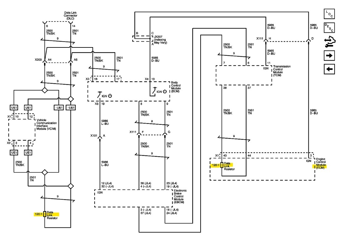
When checking the "Terminating Resistor" (which is where the 60 Ohms reading comes from), you should have the battery disconnected. 60 Ohms is the correct reading for the network, there is a slight possibility that the network is failing under a load (this is unlikely) but to be sure, disconnect the battery, disconnect the ECM connectors, and recheck the resistance at the DLC. You should now read 120 Ohms because the ECM is unplugged and out of the picture for now.
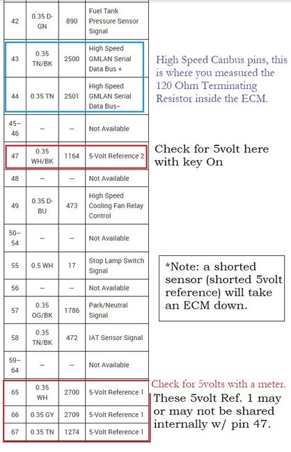
This is the oem Data network wiring for the High Speed Can bus. Note there is a resistor inside the ECM and one on its own. By disconnecting the ECM and the resistance going to 120 Ohms verifies the network is intact and we need to go after powers and grounds right at the ECM connectors.
The DLC pins 4 and 5 are both Grounds, you wont read anything on them, especially if they ground to the chassis right near where your meter is grounded.
Image (Click to enlarge)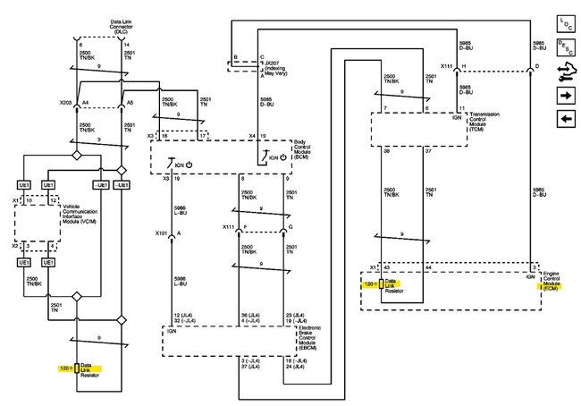
Oct 2, 2026 at 6:23 PM
Have you checked for a 12volt WakeUp call from the Body Control Module?
Images (Click to enlarge)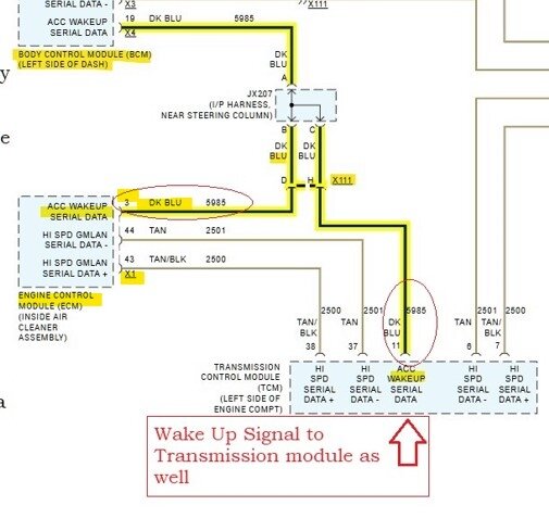
Oct 2, 2026 at 6:30 PM
I would also recommend checking the bottom of the fuse box in the engine compartment for broken, corroded, rubbed threw, etc, wires and the harness. These cars are known for these types of electrical issues. Look very closely at the under side of that fuse box. Youre missing voltage or ground somewhere.
Oct 2, 2026 at 6:35 PM
1 read 120 Ohms with battery and ecm unplug
Oct 3, 2026 at 7:28 AM
I read 119.8 ohms with ecm and batter unplug
Oct 3, 2026 at 7:28 AM
Thats good, you should also read 60 Ohms with the ECM plugged in. With a parallel circuit such as the CanBus, with a 120 Ohms terminating resistor at each end of the Can High and Can Low, the circuits resistance is divided in two and becomes 60 Ohms.
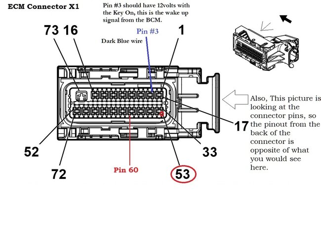
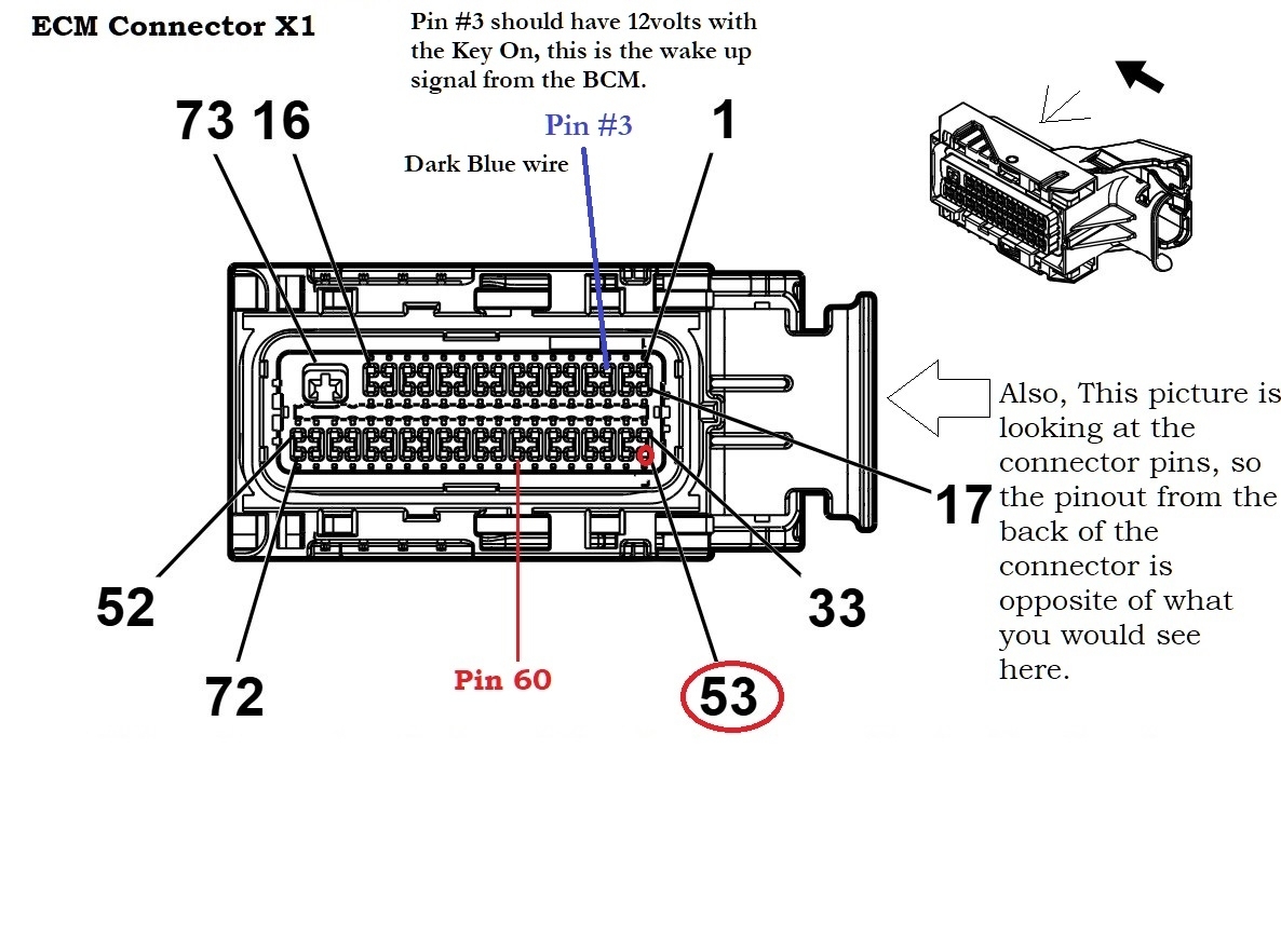
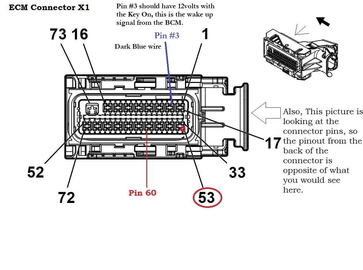
Next go to the ECM. The X1 connector is Black in color, the X2 connector is Gray encased in Black. So the X2 connector will have a color difference so you know you are checking the correct connector.
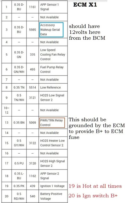
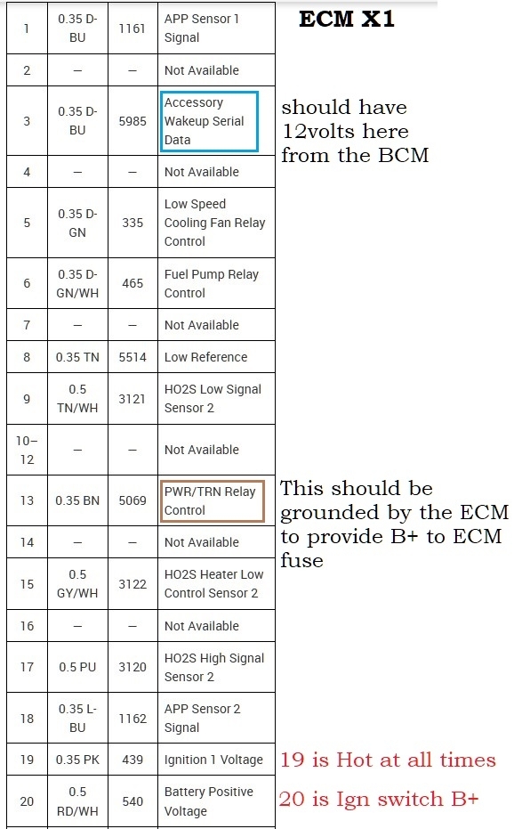
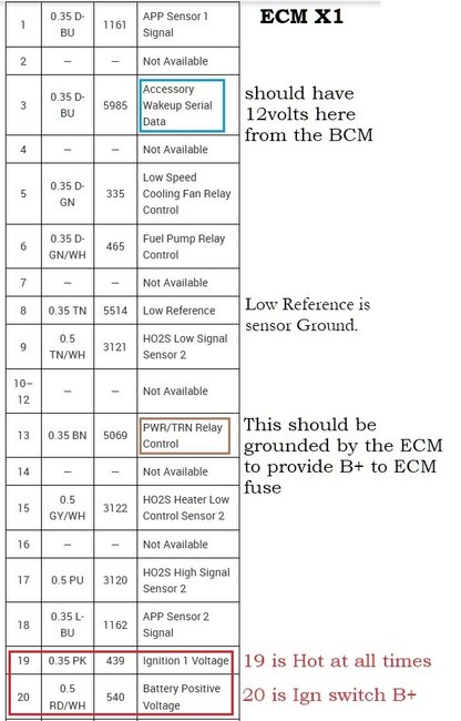
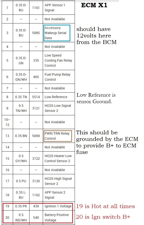
We need to check the X1 pin 3 (Dark Blue wire) for 12volts with the key On. Ignore the other things on the diagram. Just check for a Wake Up signal from the Body Control Module.
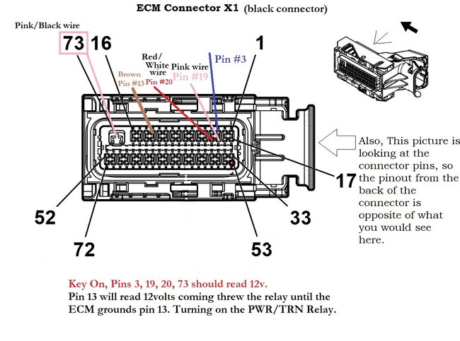
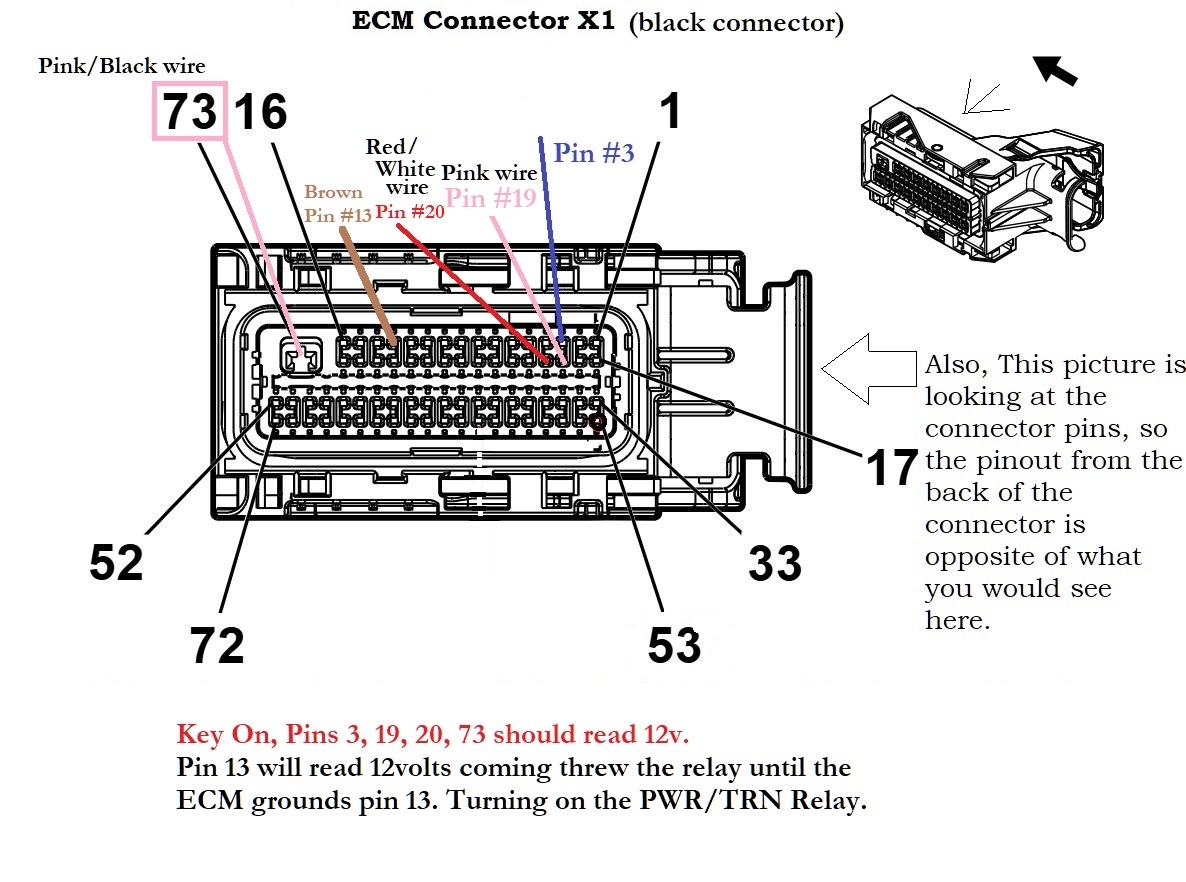
*note that the first diagram below is looking at the connector unplugged, so the picture if facing the connector pins. You will need to look for pin #3 with the Dark Blue wire. It might be necessary to take off the covers of the ECM connectors to get to the wiring at the back of the connector.
To locate pin 3, note in the pin 2 location there is nothing and pin 4 also has nothing in it. Pin 5 is a Dark Green wire. This will help you be sure you're on the correct wire.
Also note pin 13, it is the wire used by the ECM to ground the PRWTRN Relay. My guess is that you will read 12volts on that wire because the ECM is not grounding it.
If there is 12volts on pin 3, then we go to checking powers and ground at the ECM itself.
and double check the under side of the engine compartment fuse box, I have seen many broken off wires on the bottom of them.
Images (Click to enlarge)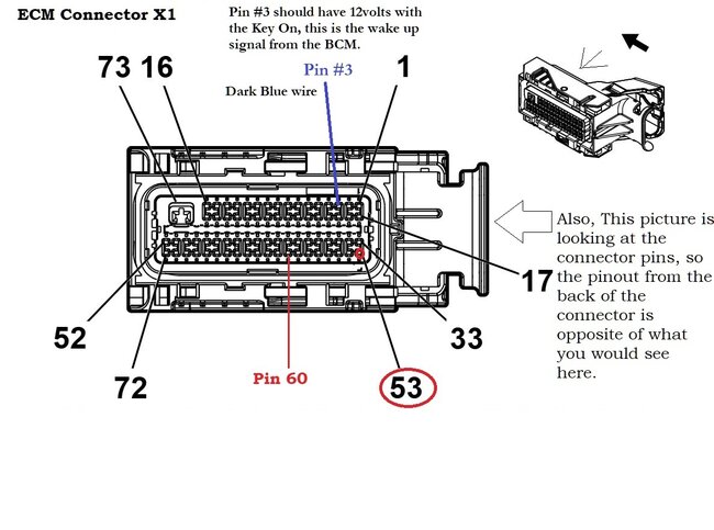
Oct 3, 2026 at 4:29 PM
12 volts with key on on blue pin 3 on PCM
Oct 4, 2026 at 7:55 AM
Ok good, now we know we're getting a signal from the BCM for the ECM to wake up. Next we need to load test each power feed and the one ground wire. Ill post the ECM pinout diagrams again, unless you just want to go back to page 1 of this question posting, I had already put up the ECM connector pinout. When you load test these wires, make sure you are only pulling power from the fuse panels and not through the ECM itself. A load test is to verify the wire can carry current, not pull high current through the ECM. I would use the 1 ECM Ground in connector X2 pin 73- as the ground for your testing. With a test light that has a higher current flow, I use a few different bulbs for load testing. A Turn signal bulb will pull a few amps of current, so I have a couple of those rigged up to load test. But use battery negative as your ground and with the key On, back probe a pin into the back of the ECM connector, and be very easy doing this, you dont want to short one ECM pin to another inside the connector. But make sure all the power wires can light the bulb bright. You dont need to leave it on there, we're just testing, not melting wires today. See where you get, and if you are unsure on anythng, please ask before testing.
Oct 4, 2026 at 9:44 AM
Ok I got a back probe kit now
Oct 4, 2026 at 10:26 AM
When back probing any connector, especially the ECM connectors, be sure the probe pin goes straight in following the wire into the connector, on some ECM connectors it is easy to accidently have the probe pin slip into the wire pin next to the one you are probing and this of course shorts the two pins together and potentially burning out the ECM. There are some vides on you tube on back probing connectors.
What do you have for tools? (ie, multimeter, oscilloscope, scan tool, back probing kit, test lights, etc).
What do you have for tools? (ie, multimeter, oscilloscope, scan tool, back probing kit, test lights, etc).
Oct 4, 2026 at 12:30 PM
multimeter, basic scan tool.back probing kit, test lights, probe tester
Oct 4, 2026 at 1:02 PM
ok Im getting ready so the ECM pinout diagrams a little easier to read. Give me a minute
Oct 4, 2026 at 2:36 PM
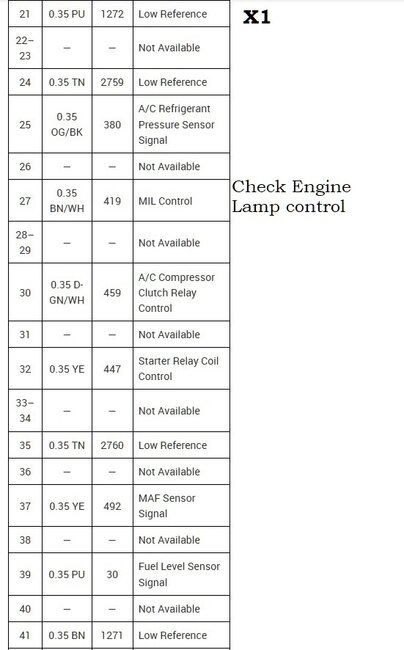
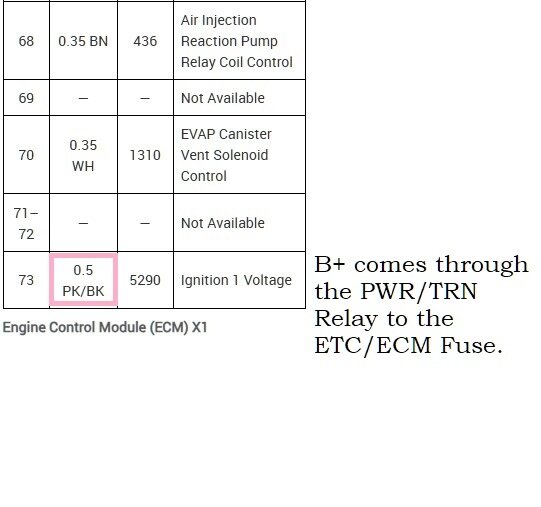
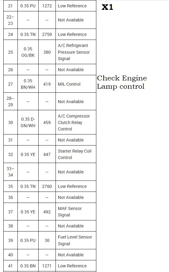
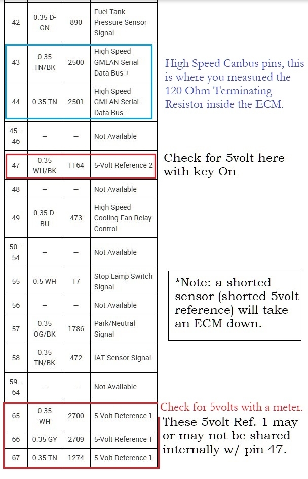
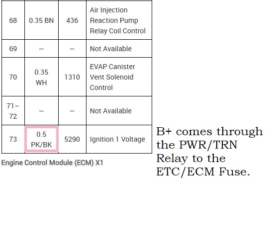
These are the ECM X1 connector pinouts, these are the wires you're load testing for power. Ground your test lamp on battery negative and back probe each power wire. Make sure it can light a Turn Signal bulb at least, not just a 12v regular test light. And double check your testing before actually loading the circuit.
The proper method would be to voltage drop the same wire you are load testing at the moment. You are just connecting the multimeter from B+ to the power wire you're on. You want to see a low voltage drop number. With the circuit loaded this is when a problem circuit will show itself.
I can make you a quick diagram if that would help.
Images (Click to enlarge)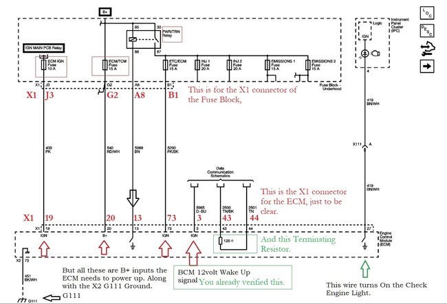
Oct 4, 2026 at 3:20 PM
Yes thanks the diagram would help
Oct 4, 2026 at 5:38 PM
🔧 Tools & Auto Repair Parts
Find automotive tools, diagnostic equipment, and replacement
parts for your next repair.
Shop on Amazon →
Paid affiliate link. As an Amazon Associate, we earn from qualifying purchases.