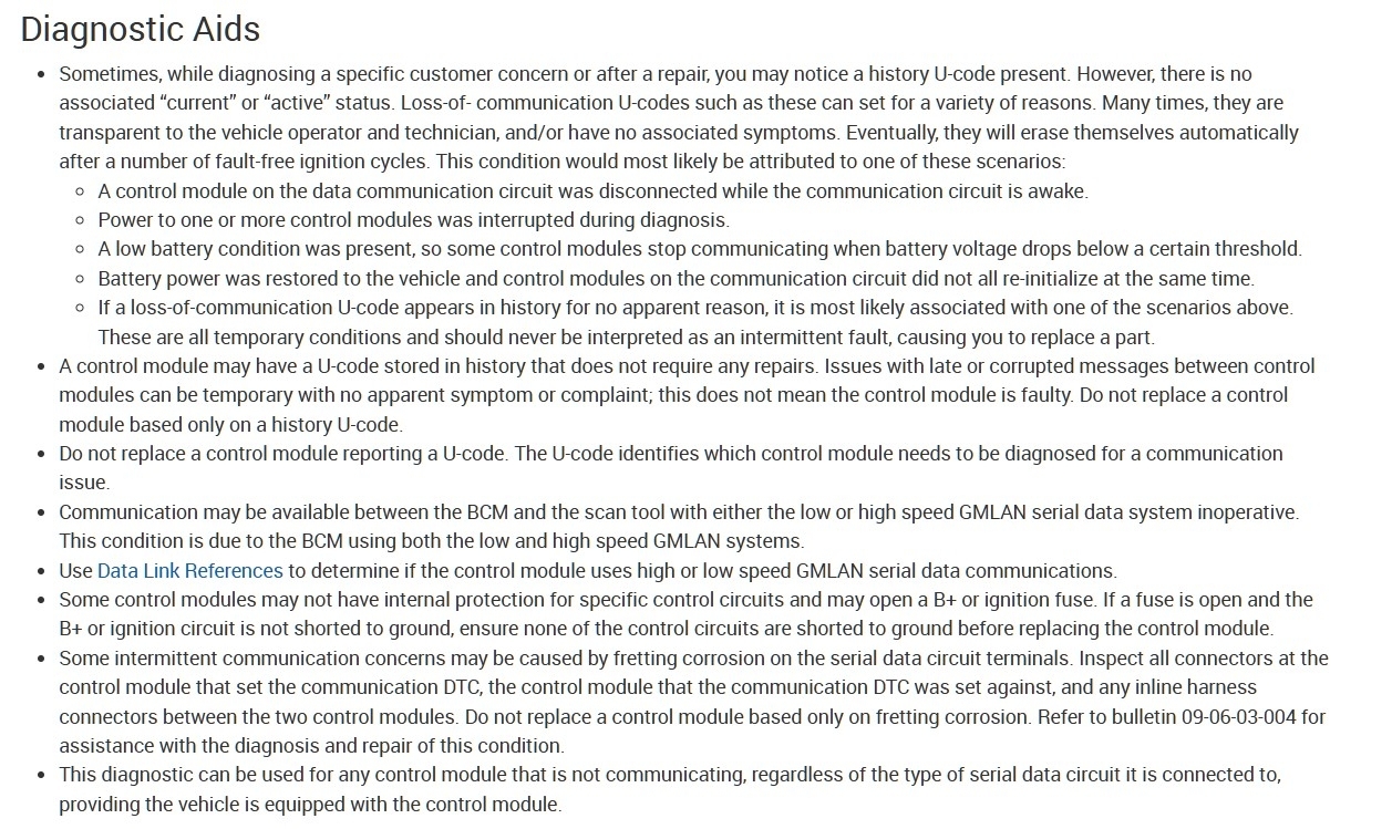
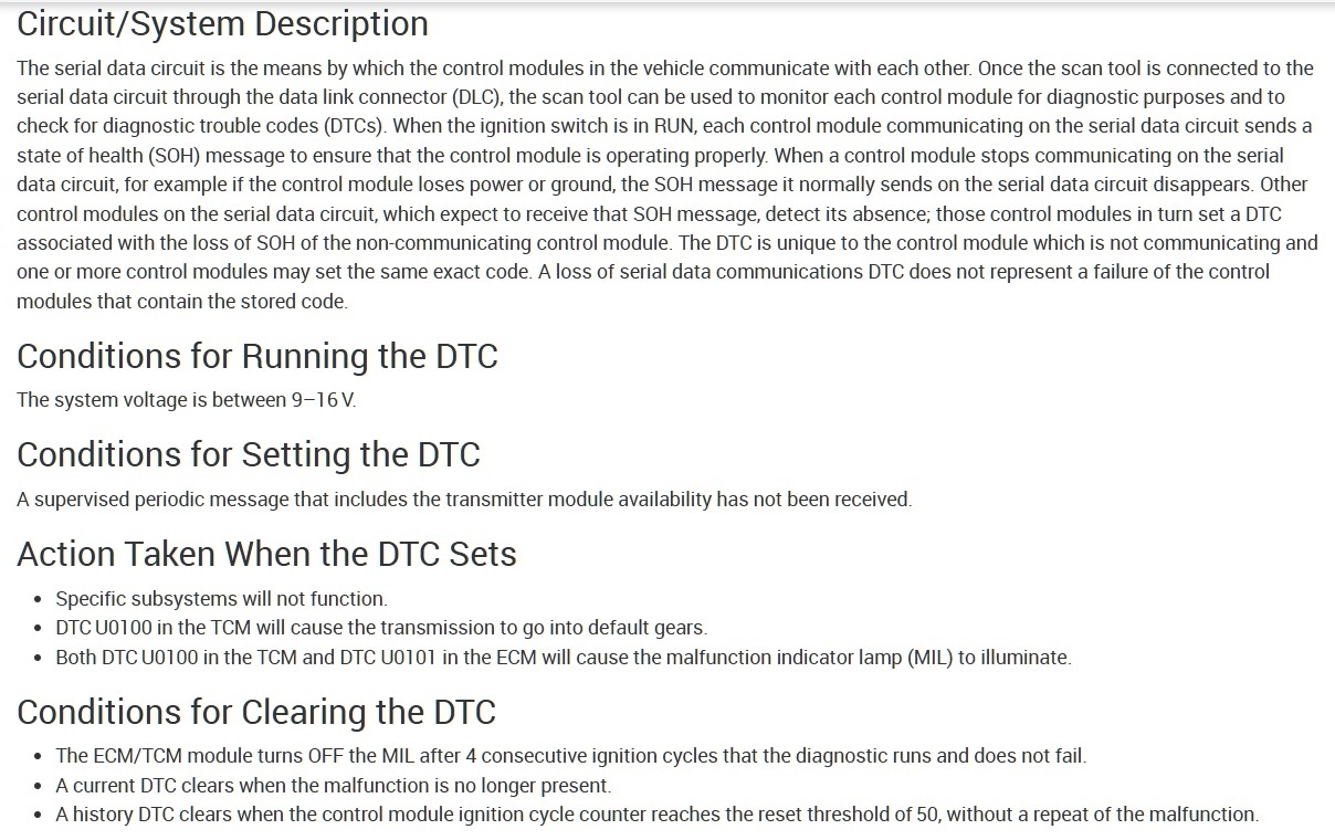
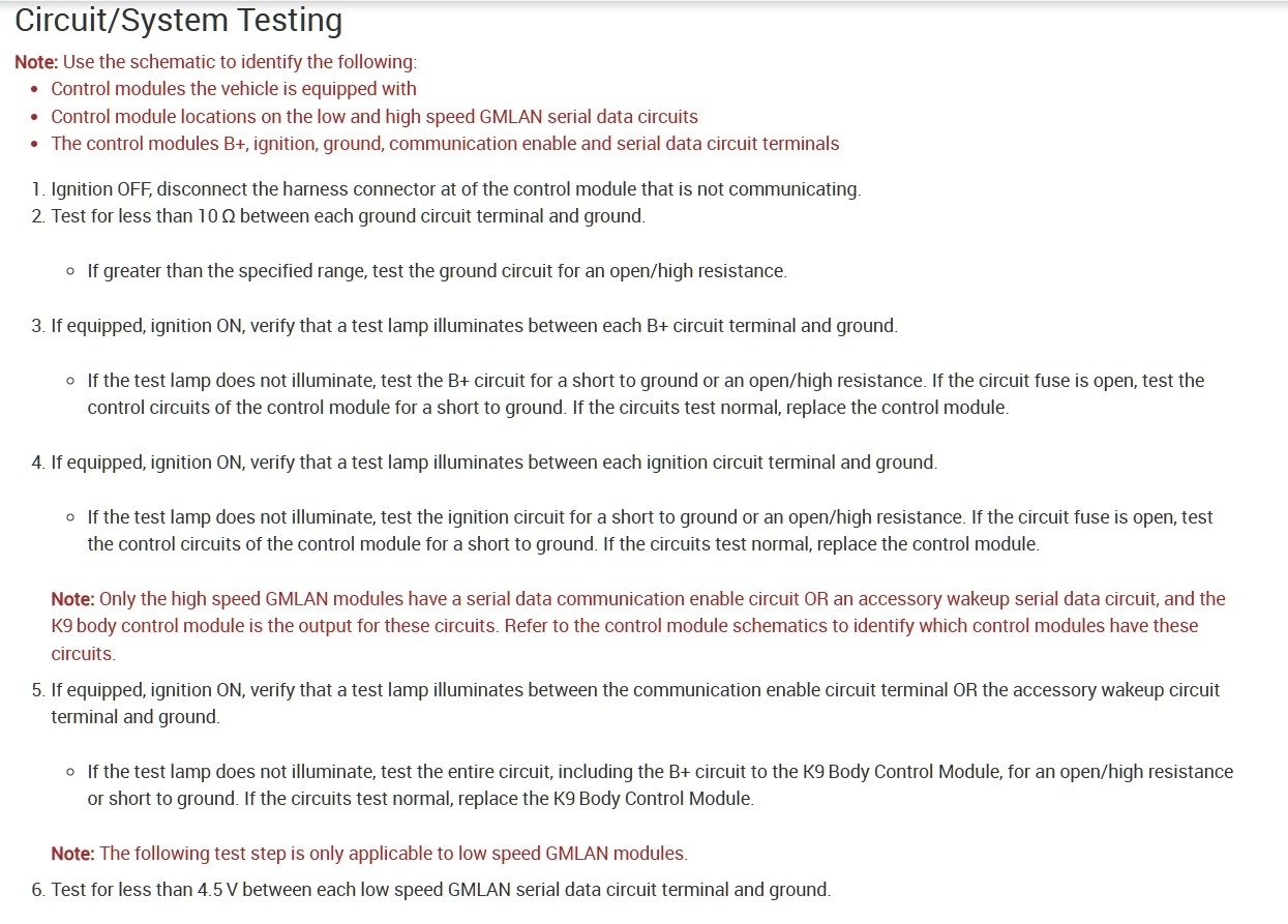
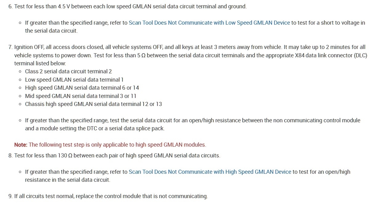
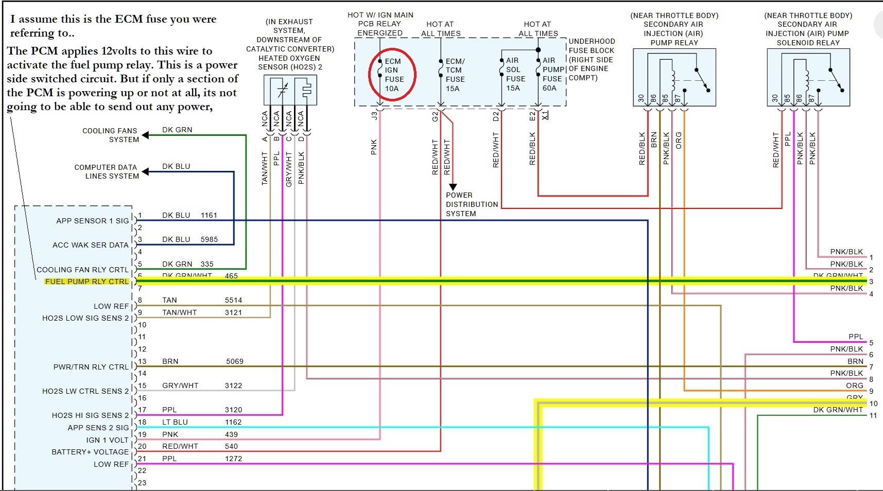
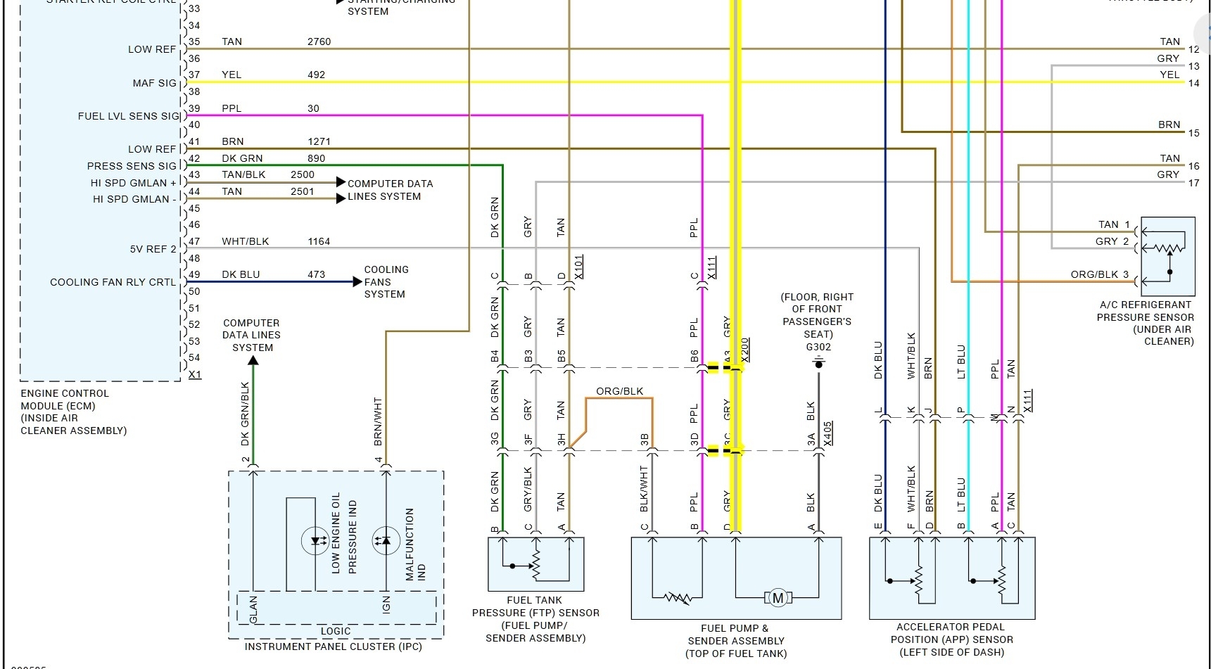
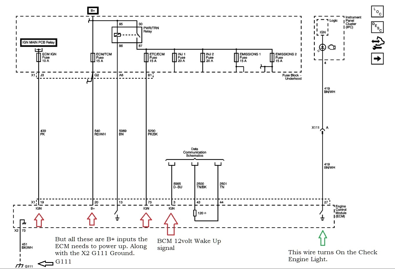
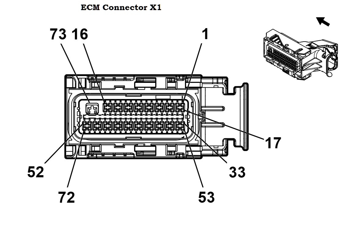
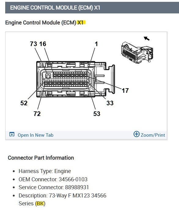
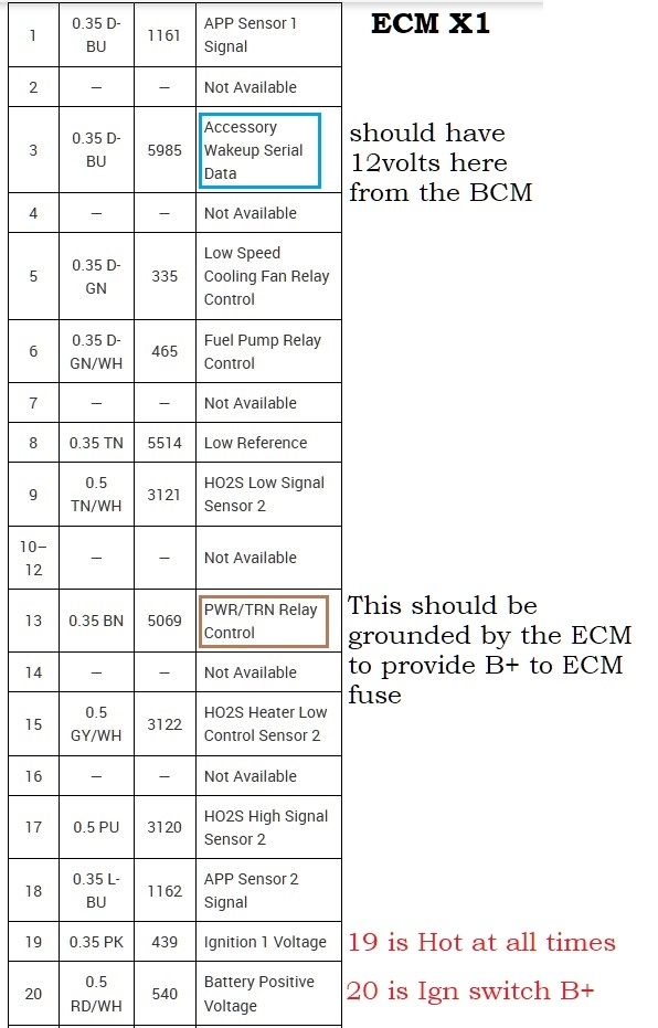
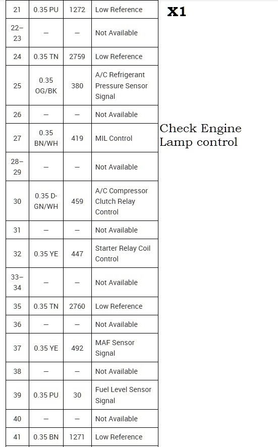
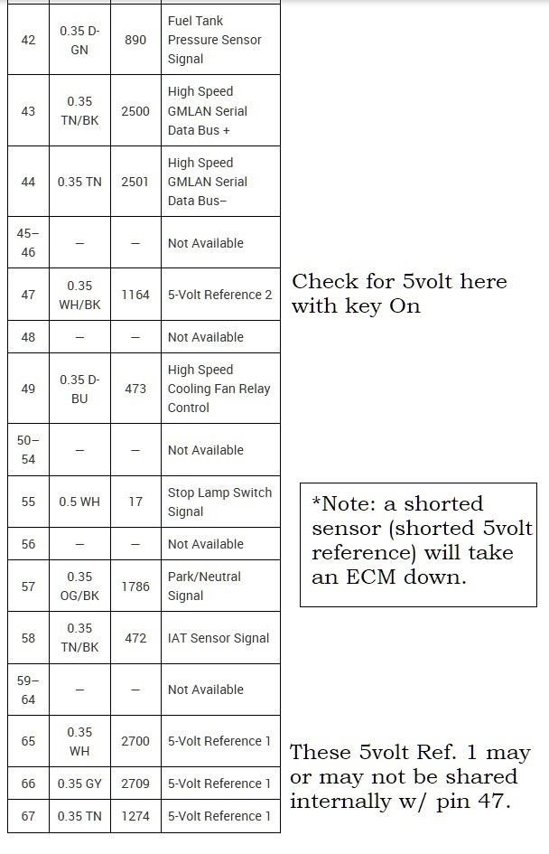
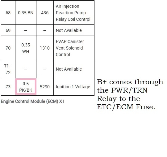
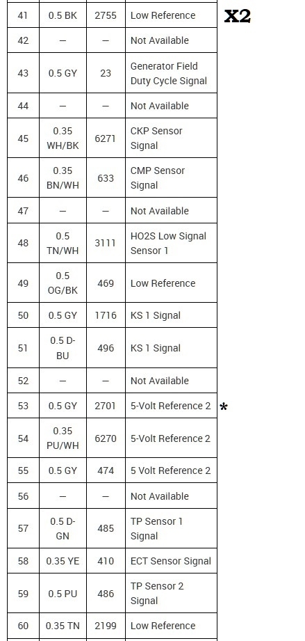
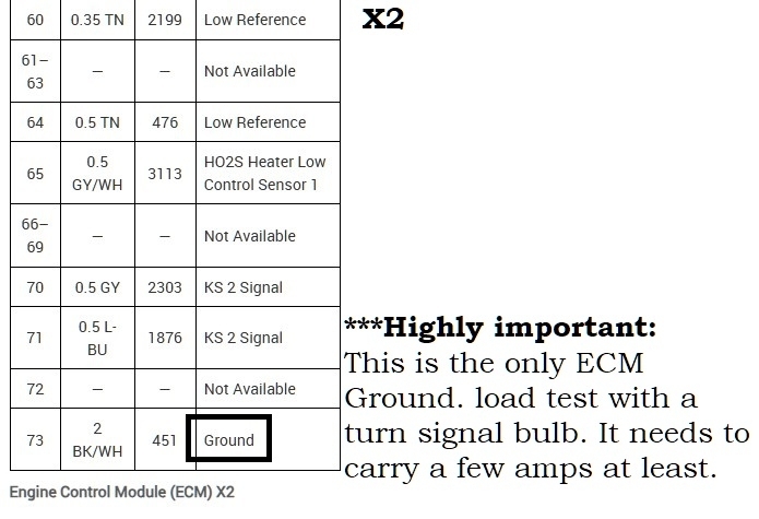
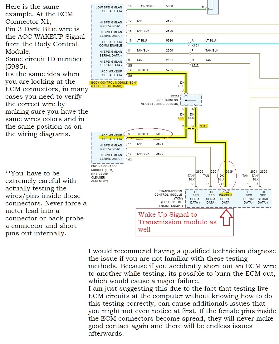
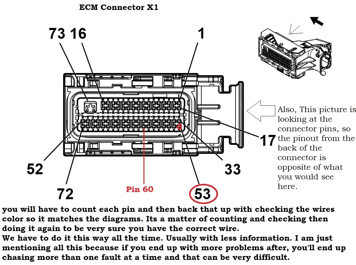
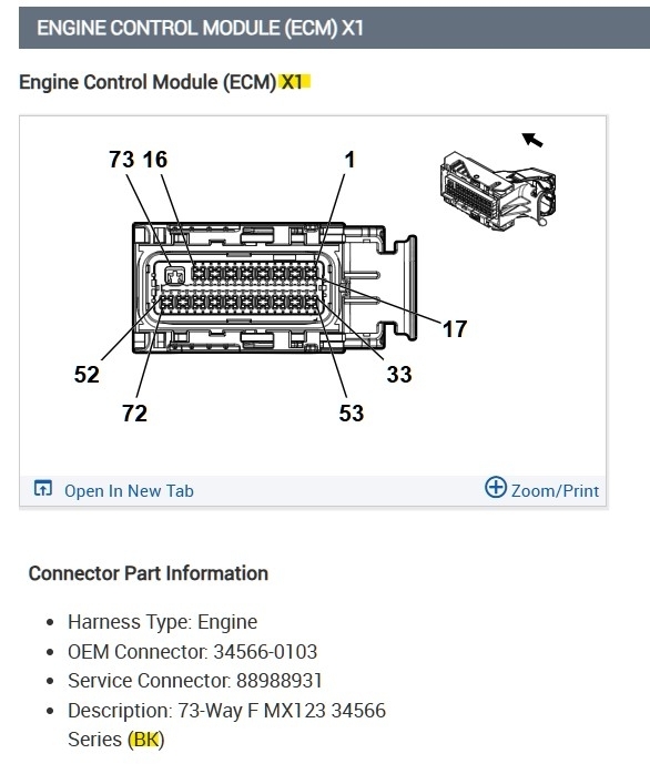
X1 is Black. There might be plastic covers on the ECM connectors that need to come off first, then you can check the wires from the back of the connector and not spread the front pins. Just dont shove meter leads into connectors, you only need to lightly touch the pins with the meter leads to get a reading. If youre power and ground test go ok with the connectors unplugged, then do a plugged in power and ground check.
So when back probing an ECM connector plugged in you have to be very careful and push the back probe in straight into the back on the connector so as not to short two of the pins together. This can happen easy without even knowing you did it. So only use back probing pins and be easy with the wiring harness.
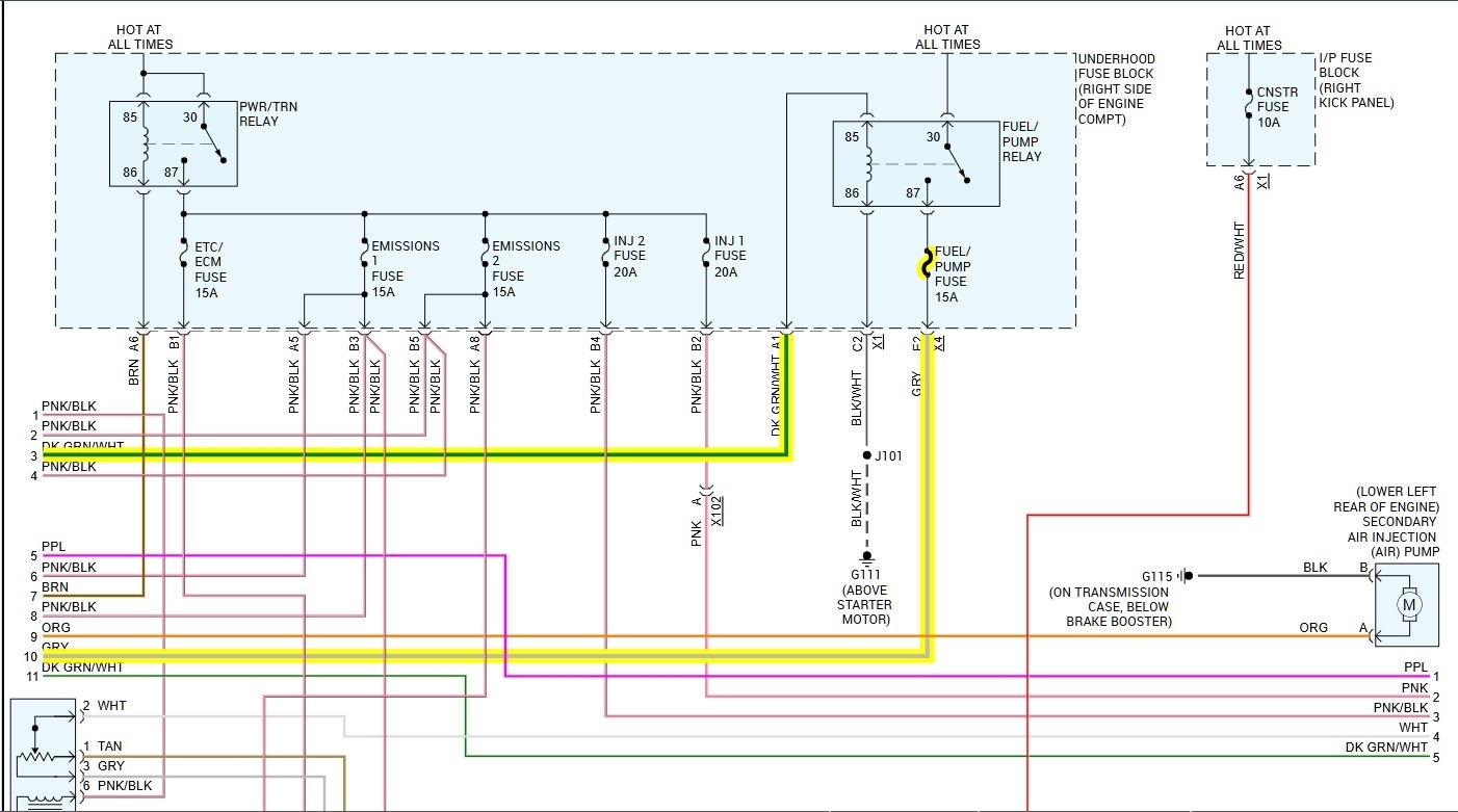
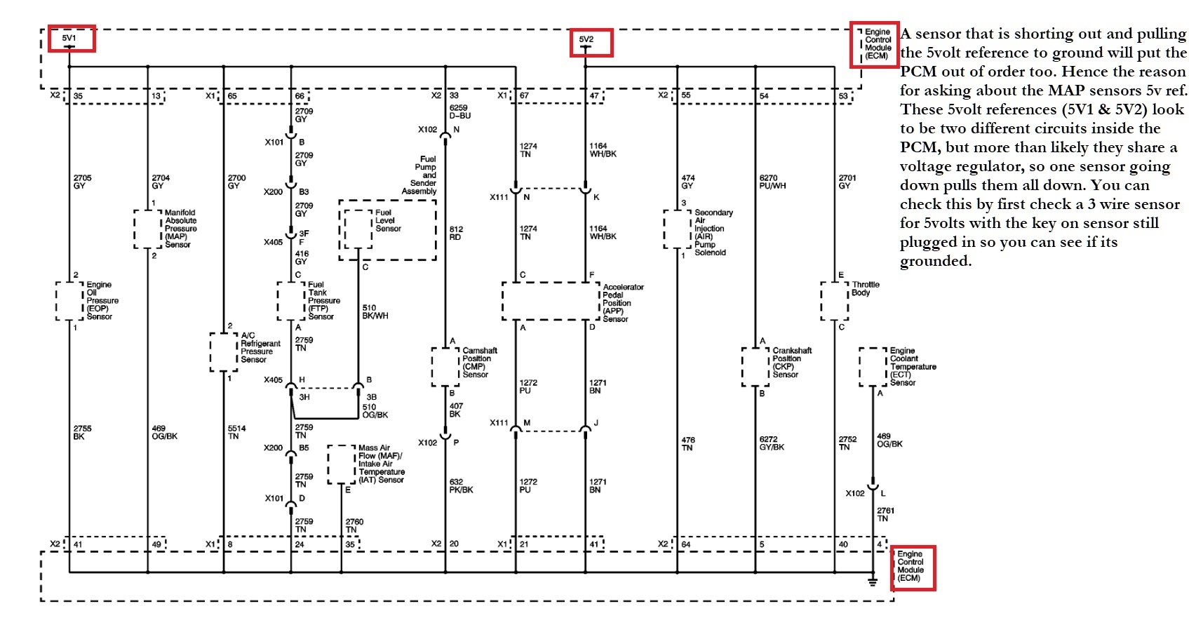
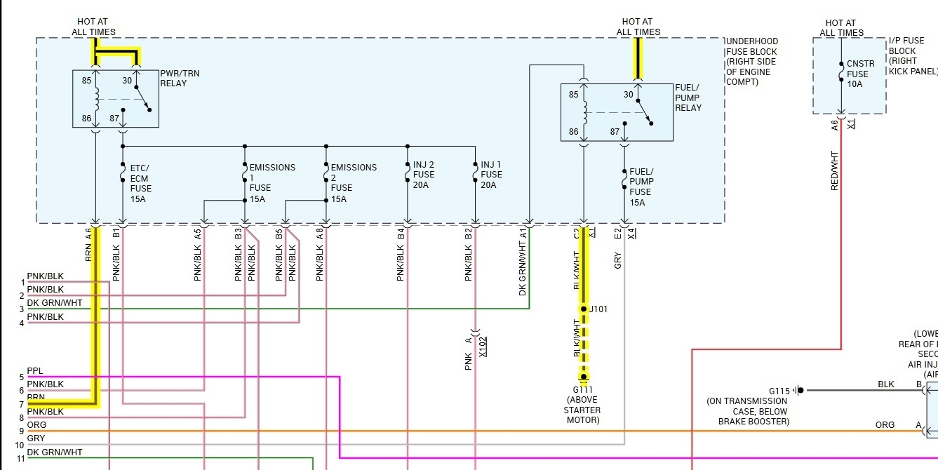
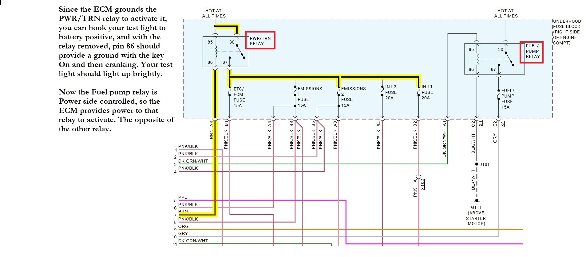
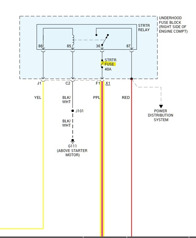
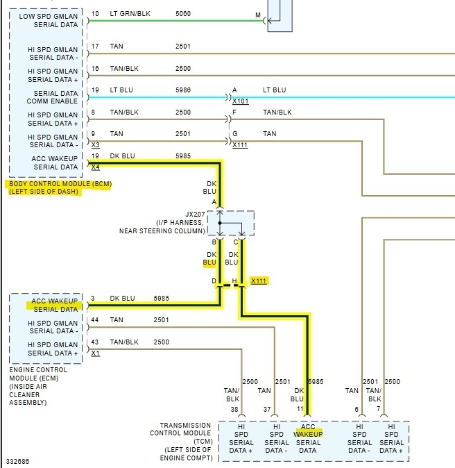
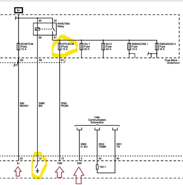
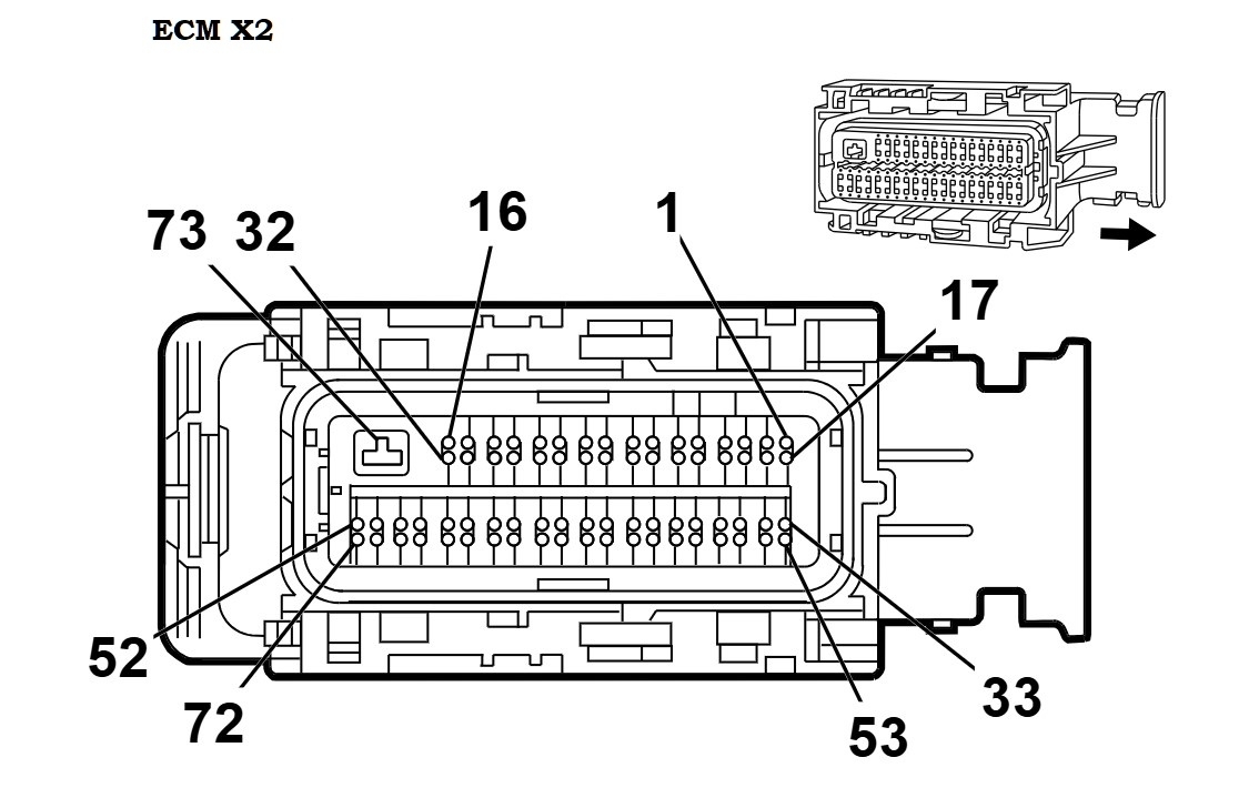
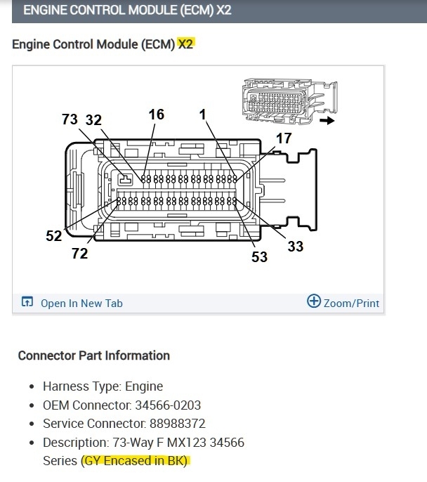
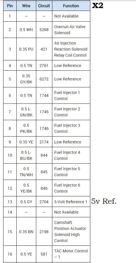
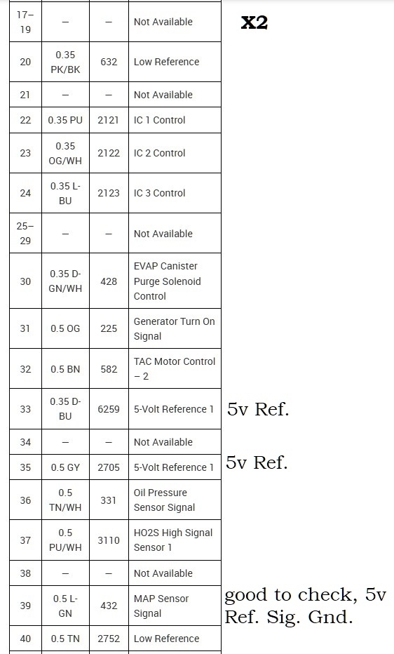
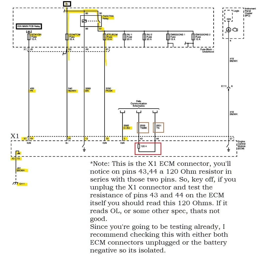
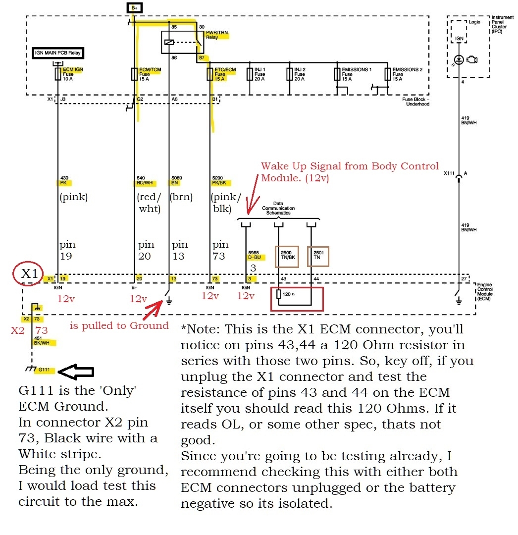
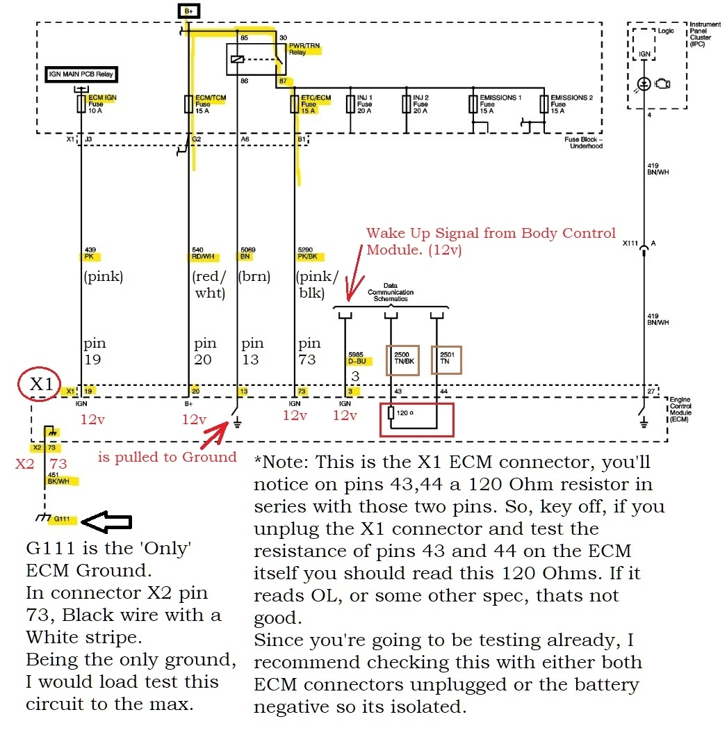
The 2 diagrams below are the ones you need to work with first. The X1 connector has the power feeds, but note that the only Ground for the ECM is in connector X2 pin 73, Ground G111 is a Black/White wire.
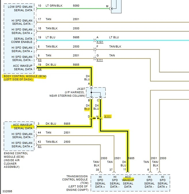
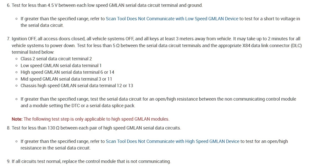
Take notice of the internal Terminating Resistor for the ECM, its two pins 43, 44 in the X1 connector, with both the connectors unplugged, measure the resistance across the ECMs pins 43 & 44. You should read 120 Ohms roughly. This is a quick check of the resistor while you're already right there, but the key needs to be off when checking resistance even though the ECM is unplugged, its just a good thing to remember.
You are looking for the Black X1 connector and yes it will have some higher gauge wires because those are the power feeds.
Images (Click to enlarge)
Sep 24, 2026 at 8:55 AM