Hello .. thanks for the donation .. much appreciated
Hope this helps .. let me know if you need any more information
Automatic A/C-heater system consists of electronically controlled components added to standard air conditioning system. Automatic A/C system is controlled by the auto amplifier. See Fig. 1
Fig. 1: A/C System Control Panel ID (Auto Amplifier)
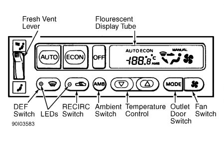
Auto amplifier unit is a switch control panel and microcomputer assembly. It processes various sensor information and controls air mix door, fan speed, outlet door, intake door, A/C compressor clutch, memory function and water cock (heater control valve) solenoid.
NOTE:For A/C-heater components not covered in this article, refer to MANUAL A/C-HEATER SYSTEM article in the AIR CONDITIONING & HEAT Section.
OPERATION
Automatic A/C-heater system controls optimum airflow (fan speed), outlet air temperature and outlet air vents to maintain vehicle interior temperature at desired setting.
AIR MIX DOOR MOTOR
Air mix door motor is attached to heater unit. Auto amplifier commands air mix door motor to rotate a shaft to move air mix door to a set position/angle. Air mix door position/angle is monitored by Potentiometer Balance Resistor (PBR), located inside air mix door motor. Door position/angle is continuously being fed back to auto amplifier by PBR to allow auto amplifier to move door position/angle for desired temperature.
AMBIENT TEMPERATURE SENSOR
Ambient temperature sensor, located below hood latch, detects ambient (outside) temperature and converts this reading into a resistance value read by the auto amplifier. See Fig. 2 .
If auto amplifier detects an abrupt change, it gradually adjusts interior temperature (.6 °F per 100 seconds) until desired setting is reached. If vehicle stops in traffic after highway speeds, ambient temperature sensor detects high temperature from heat off radiator. To counteract this sudden temperature change, ambient temperature input process (inside auto amplifier) gradually adjusts interior temperature to prevent an unpleasant temperature changes.
ASPIRATOR
Aspirator, located on lower, front of heater unit, produces a vacuum from outlet air discharged from heater unit. This aspirator vacuum pulls air from driver's side area, through in-vehicle temperature sensor.
AUTO AMPLIFIER
A/C system control panel (auto amplifier), is a microcomputer that monitors and processes information from various sensors. Auto amplifier controls air mix door motor, mode door motor, intake door motor, fan motor and compressor clutch operation. Self-diagnostic functions are built into auto amplifier to check A/C system malfunctions. See Fig. 1 .
Auto amplifier detects sensor voltage differences by monitoring an internal, fixed resistor for each sensor. Each sensor is fed 5-volts through the fixed resistor by a constant voltage circuit within auto amplifier. Voltage is then applied to ground through sensor resistance. This resistance value is the input read by auto amplifier.
SELF-DIAGNOSTICS
NOTE:During all self-diagnostic functions, ensure fresh air vent on auto amplifier is in OFF position, unless otherwise indicated. Also see TROUBLE SHOOTING in this article.
SELF-DIAGNOSTIC INFORMATION PRELIMINARY INFORMATION
To properly diagnose this system, self-diagnostics should be performed in the following order:
Read ENTERING/EXITING SELF-DIAGNOSTICS.
Perform SELF-DIAGNOSIS STEPS 1-5.
Perform appropriate PRELIMINARY CHECK chart under TROUBLE SHOOTING CHARTS for symptom diagnosis. PRELIMINARY CHECK charts refer to proper DIAGNOSTIC PROCEDURE chart(s).
Perform DIAGNOSTIC PROCEDURE chart(s) under TROUBLE SHOOTING CHARTS.
ENTERING/EXITING SELF-DIAGNOSTICS
Start engine and immediately depress and hold OFF switch on auto amplifier for at least 5 seconds. DO NOT enter self-diagnostics without engine running.
Select self-diagnosis steps 1-5 by pressing temperature control switches. After selecting step 5, auxiliary mechanism test may be selected by pressing FAN switch. Auxiliary mechanism test checks temperature setting trimmer.
To cancel self-diagnostics, press AUTO switch or turn ignition to OFF position.
SELF-DIAGNOSIS STEP 1
Checks Light Emitting Diodes (LEDs) & Segments
Step 1 starts automatically when self-diagnostics are entered. All LEDs and fluorescent display tubes should illuminate. See Fig. 1 . If all LEDs and fluorescent display tubes DO NOT illuminate, repair or replace as necessary. If LEDs and fluorescent display tubes test okay, replace auto amplifier.
SELF-DIAGNOSIS STEP 2
Checks Sensors For Open/Short Circuits
Position vehicle to enable sunlight to shine on sunload sensor. Enter self-diagnosis step 2 by pressing UP temperature control switch on auto amplifier. Display will illuminate a 2. If all sensor circuits are okay and no trouble codes are present, display will change to Code 20. It takes auto amplifier about 4 seconds to check all sensor circuits.
If a sensor circuit is faulty, circuit code number will flash on display. Shorted circuit will have a flashing "--" in front of the number 2. Open circuit will NOT have a flashing "--". If, for example, 21 is displayed on auto amplifier by an illuminated 2 and a flashing 1, an open circuit is indicated.
If two sensor circuits are faulty, each circuit code number will blink twice. See SELF-DIAGNOSIS STEP 2 CODE EXPLANATIONS TABLE to determine what a code number means.
SELF-DIAGNOSIS STEP 2 CODE EXPLANATIONS
Code....Sensor
20.......No Trouble Codes
21.......Ambient Temperature Sensor
22.......In-Vehicle Temperature Sensor
24.......Intake Sensor
25.......Sunload Sensor
26.......Potentiometer Balance Resistor (PBR)
SELF-DIAGNOSIS STEP 5
Checks Temperature Detected By Sensors
To enter self-diagnosis step 5, press UP temperature control switch on auto amplifier. Display will illuminate a 5. When DEF switch is pressed once, display will show temperature detected by ambient temperature sensor.
Press DEF switch again, display will show temperature detected by in-vehicle sensor. Press DEF switch again (3rd time), display will show temperature detected by intake sensor.
Press DEF switch again (4th time), display will return to 5. If temperature shown on display is greatly different from actual temperature, inspect sensor circuit. If sensor circuit is okay, check sensor. See appropriate sensor under TESTING.
AUXILIARY MECHANISM SETTING
Temperature Setting Trimmer
Temperature setting trimmer compensates for small differences between temperature setting on display and actual temperature within a range of +/-6 °F (+/-3 °C).
With system in SELF-DIAGNOSIS STEP 5, press FAN switch. System is now in auxiliary mode to set trimmer. Each time UP or DOWN temperature control switch is pressed, temperature display changes in one (1 ) degree Fahrenheit increments.
NOTE:If battery is disconnected, temperature trimmer setting goes to 0 ° on both Fahrenheit and Celsius scale and will have to be reset.
Monday, September 23rd, 2019 AT 6:23 PM
(Merged)
