Hello -
If the car is running just fine. . .. . .I wouldn't worry about changing anything. I have attached info on checking out the knock sensor. Though I gave you steps for the harness and sub-harness, I would just start with the component check out.
DTC P0325 - KNOCK SENSOR
1. Check Knock Sensor Harness Input Signal Circuit
Loosen and retighten engine ground screws. Turn ignition off. Disconnect ECM harness connector and knock sensor harness connector. See Fig. 2 and Fig. 11 . Using an ohmmeter, check continuity between knock sensor harness connector terminal No. 1 (White wire) and ECM harness connector terminal No. 64. If no continuity exists, repair open in White wire. If continuity exists, go to next step.
2. Check Knock Sensor Sub-Harness Input Signal Circuit
Using an ohmmeter, measure resistance between knock sensor sub-harness connector terminal No. 1 (White wire) and ground. Resistance should be 500-620 k/ohms. If resistance is as specified, check for fault in White wire. If resistance is not as specified, go to next step.
3. Check Component
Using an ohmmeter, measure resistance between sensor terminal No. 2 (White wire) and ground. If resistance is not 500,000-620,000 ohms, replace knock sensor. If resistance is within specified range, disconnect ECM wiring harness connector. Check ECM pin terminals for damage or corrosion. Repair if necessary and perform FINAL CHECK.
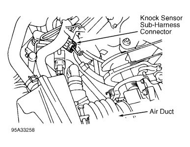
Fig. 11: Locating Knock Sensor Sub-Harness Connector
Courtesy of NISSAN MOTOR CO., U.S.A.
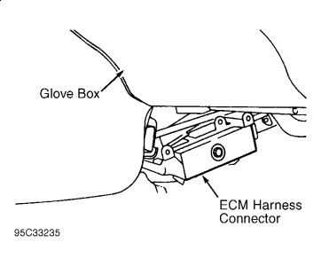
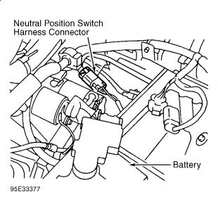
I again have attached info for the Neutral Position Switch. I again would start with the Component checkout.
DTC P0705 - PARK/NEUTRAL POSITION SWITCH
NOTE: Steps 1-3 are for M/T models. For A/T models, go to step 4.
1. Check Ground Circuit
Turn ignition off. Disconnect neutral position switch harness connector. See Fig. 24. Using an ohmmeter, check continuity between harness connector terminal No. 4 (Black wire) and body ground. If no continuity exists, repair open Black wire. If continuity exists, go to next step.
2. Check Input Signal Circuit
Disconnect ECM harness connector. See Fig. 1. Using an ohmmeter, check continuity between neutral position switch harness connector terminal No. 2 (Green/White wire) and ECM harness connector terminal No. 22. If no continuity exists, repair open in Green/White wire. If continuity exists, go to next step
3. Check Component
Disconnect neutral position switch harness connector. Using an ohmmeter, check for continuity as follows:
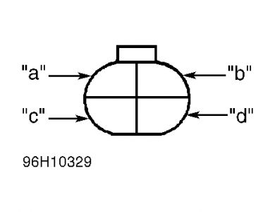
"� With gear selector in Reverse, continuity should be present terminals 2 and 4.
"� With gear selector in Neutral, continuity should be present terminals 1 and 3.
"� With gear selector in any other position, continuity should not be present between terminals.
See Fig. 22.
If continuity is not as specified, replace neutral position switch. If continuity is as specified, check ECM pins and terminals for damage and check connection of ECM harness connector. Reconnect ECM harness connector and retest.
Fig. 22: Identifying Neutral Position Switch Harness Connector Terminals
Courtesy of NISSAN MOTOR CO., U.S.A.
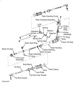
As for the rack leaking. It does have seals and O'rings that can be replaced. Sometimes depending on the cost it is better to replace the entire rack just because all of the parts are worn, not just the seals.
I can provide directions on the removal and installation on that if you would like.
I can also provide directions on the removal of the stabilizer bar if you would like that.
Monday, March 30th, 2009 AT 10:38 AM


