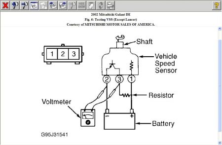
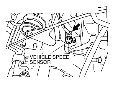
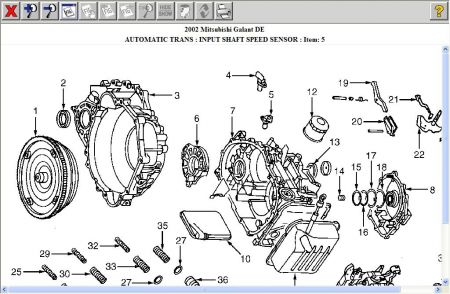
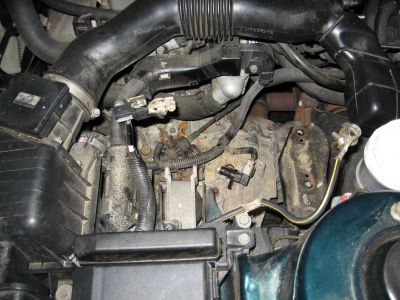
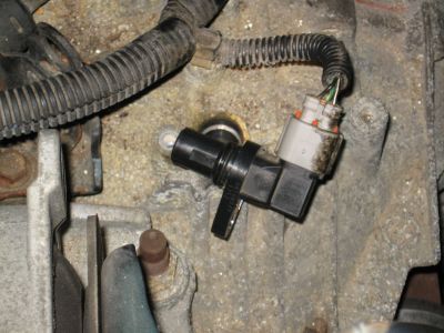
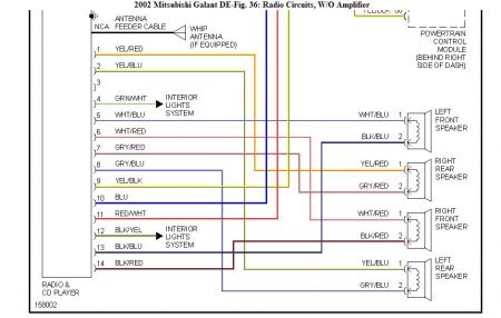
So we can rule out the speed sensor and its circuit to the PCM.
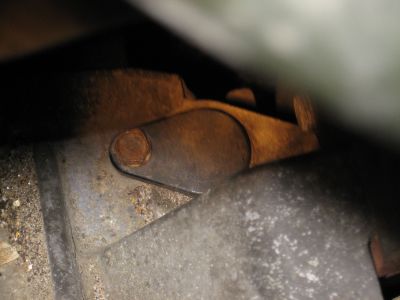
I just checked through another area of my database and it seems the speed sensor is stated as on the side of trans-axle, near firewall, maybe you can check that out to confirm, just out of curiosity and for future reference and some portion of testing requires unplugging the connections.
Anyway, I will provide a complete diagnostic procedures for you to check through and hope an answer is found.
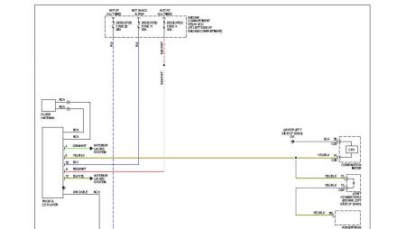
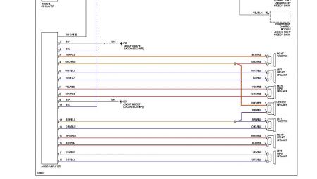
PS. After going through the diagnostic procedure, I believe your radio is the cause of the problem. Refer to # 10
Speedometer does not work:
1. Connect scan tool to data link connector, check for Diagnostic Trouble Code (DTC). If DTC P0500 (Vehicle Speed Sensor) is set, diagnose this DTC first. Go to step 6. If DTC P0500 is not set, go to next step.
2. On Eclipse, if trip odometer is not working normally, go to next step. If trip odometer is working normally go to step 5. On Galant, if tachometer is not working normally, go to next step. If tachometer is working normally, go to step 5
3. Disconnect instrument cluster connector. Turn ignition switch to ON position. Connect DVOM between ground and instrument cluster connector terminal No. 52 (Black/White wire) on Eclipse or terminal No.29 (Black/White wire) on Galant. If battery voltage is present, go to next step. If battery voltage is not present, check harness connectors and harness wiring between instrument cluster and ignition switch for damage. Repair as necessary.
4. Using a DVOM, check resistance between ground and instrument cluster harness connector terminal No. 34 (Black wire) on Eclipse or terminal No. 30 (Black wire) on Galant. If resistance is less than 2 ohms, replace instrument cluster printed circuit board or speedometer and tachometer. If resistance is greater than 2 ohms, check instrument cluster connector and harness wiring. Repair as necessary. If connector and wiring are okay, go to next step.
5. Disconnect vehicle speed sensor connector and instrument cluster connector. Turn ignition switch to ON position. Connect DVOM between ground and harness side of instrument cluster connector terminal No. 29 (White/Blue wire) on Eclipse or terminal No. 16 (Yellow/Black wire) on Galant. Voltage should be 5 volts. If voltage is okay, repair or replace instrument cluster printed circuit board or speedometer and tachometer. If voltage is not 5 volts, check instrument cluster connector and harness wiring. Repair as necessary. If connector and wiring are okay, go to next step.
6. Disconnect vehicle speed sensor harness connector and connect DVOM to harness side. Check vehicle speed sensor power supply voltage between terminal No. 1 (Black/White wire) on Eclipse or (Black/Blue wire) on Galant and ground. Battery voltage should be present. If voltage is okay, go to next step. If voltage is not present, check vehicle speed sensor harness connector and wiring. Repair as necessary.
7. Using DVOM, check resistance between ground and vehicle speed sensor harness connector terminal No. 2 (Black wire). Resistance should be less than 2 ohms. If resistance is greater than 2 ohms, check instrument cluster connector and harness wiring. Repair as necessary. If connector and wiring are okay, go to next step.
8. Disconnect vehicle speed sensor harness connector. Connect DVOM between ground and harness side terminal No. 3 (White/Blue wire) on Eclipse or (Yellow/Black wire) on Galant. If 9 volts are not present, check vehicle speed sensor harness connector and wiring. Repair as necessary. If 9 volts are present, go to next step.
9. Check harness wiring between vehicle speed sensor connector to radio and tape player connector, auto-cruise control ECU ECM (M/T) or PCM (A/T) connector and instrument cluster connector. If connectors or wiring are damaged, repair as necessary. If connectors and wiring are okay, go to next step.
CAUTION: To prevent damage to scan tool, always turn ignition off before connecting or disconnecting scan tool.
NOTE: If ECM (M/T) or PCM (A/T) is replaced, immobilizer-ECU should also be replaced. Each ECM (M/T) or PCM (A/T) has an encrypted code for immobilizer-ECU, and is registered in immobilizer-ECU.
10. Connect scan tool to data link connector. Turn ignition switch to ON position. Read DTC. Disconnect radio and tape player connector. If DTC P0500 does not reset, replace radio and tape player. If speedometer does not work, disconnect auto-cruise control ECU connector. If DTC P0500 does not reset, replace auto-cruise control ECU. If speedometer does not work, disconnect instrument cluster harness connector. If DTC P0500 does not reset, replace instrument cluster. If DTC P0500 resets when any connector is disconnected, replace ECM (M/T) or PCM (A/T).
Saturday, December 13th, 2008 AT 9:59 PM


