This is for the 93 Jeep, I will aslo look up the car But I need the model?
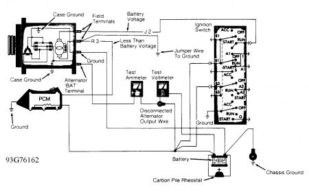
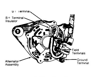
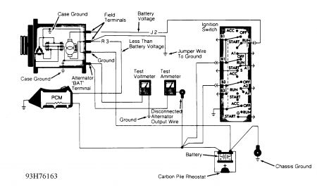
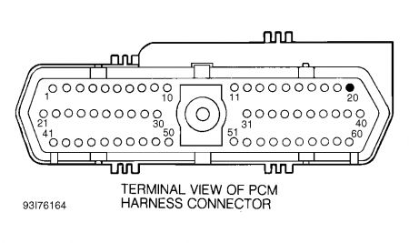
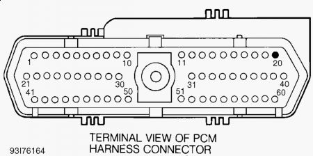
TEST CH-2, ALTERNATOR FIELD NOT SWITCHING PROPERLY (CODE 41 ) 1. Put DRB-II in voltmeter mode. Check voltage of Automatic Shutdown (ASD) circuit by probing Dark Green/Orange wire (Dark Green/Black wire on Grand Cherokee and Grand Wagoneer) at back of alternator. If voltage is less than 10 volts, repair open circuit from ignition switch. If voltage is 10 volts or greater. go to next step. 2. Check voltage of alternator field driver circuit by probing Dark Green wire at back of alternator. If voltage is less than 10 volts, go to next step. If voltage is 10 volts or greater, go to step 6). 3. Turn ignition off. Disconnect and inspect PCM connector. Repair, if necessary. Disconnect alternator harness from back of alternator. Using an external ohmmeter, check field driver circuit (Dark Green wire) for resistance. If resistance is less than 5.0 ohms, replace PCM. If resistance is 5.0 ohms or greater, repair open in Dark Green wire. 4. Turn ignition off. Disconnect PCM connector. Disconnect alternator harness from back of alternator. Using an external ohmmeter, check for resistance between alternator field terminals. If resistance is 5.0 ohms or greater, replace alternator. If resistance is less than 5.0 ohms, go to next step. 5. With DRB-II in ohmmeter mode, check resistance in field circuit of alternator harness. If resistance is 5.0 ohms or greater, repair short to ground in field driver circuit (Dark Green wire). If resistance is less than 5.0 ohms, replace PCM. 6. Turn ignition off. Disconnect PCM connector. Disconnect alternator harness from back of alternator. Using an external ohmmeter, check for resistance in field driver circuit alternator harness terminal and cavity No. 20 on PCM connector. See Fig. 4 . If resistance is 5.0 ohms or greater, repair short to ground in field driver circuit (Dark Green wire). If resistance is less than 5.0 ohms, replace PCM. Perform CHARGING VERIFICATION (CH-VER) test. NOTE: Perform TEST CH-1, BATTERY CONDITION CHECK before proceeding.
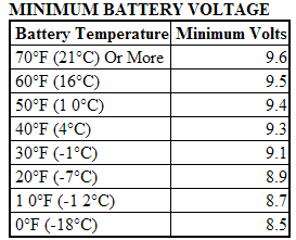
TEST CH-1, BATTERY CONDITION CHECK 1. If battery has a built-in hydrometer, go to step 2). Turn ignition and all accessories off. Ensure battery voltage is 12.0 volts or greater. If voltage is less than 12.0 volts, charge battery and go to step 3). 2. If battery hydrometer is Green, go to step 3).1f battery hydrometer is Yellow or a bright color, replace battery and perform CHARGING VERIFICATION (CH-VER) test. If battery hydrometer is dark in color, charge battery and go to next step. 3. Ensure battery cables, terminals and posts are clean and tight. Perform a battery load test by applying a 300-amp load for 15 seconds. Wait 15 seconds to allow battery to stabilize. Apply a load equal to 50 percent of battery cold cranking rating for 15 seconds and record minimum voltage reading. 4. See MINIMUM BATTERY VOLTAGE table. If battery is below volt age, replace battery and perform CHARGING VERIFICATION (CH-VER) test. If voltage reading is okay, go to next step. NOTE: Perform PRELIMINARY CHECKS under TROUBLE SHOOTING before proceeding. If battery shows signs of freezing or leakage, battery posts are loose or battery has low electrolyte level, DO NOT test.
Saturday, October 3rd, 2009 AT 7:16 AM
