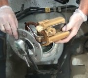
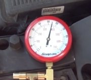
Without any specific criteria it would be almost impossible to get information as the amount is vast so whatever information that you require, let me know so I can search for them. I will see what I can get about the principles of operations.
You mentioned the first mechanic lost it so I do not know if the trouble codes then was the same P0191 or it could have been others.
P0191 - Fuel Rail Pressure (FRP) sensor circuit performance. The test procedures are below.
NOTE:
On CNG models, if vehicle is a no-start, go to TEST HB
16) KOEO/KOER DTC P0191
DTC P0191 indicates FRP voltage signal is more than self-test maximum.
Possible causes for this fault are:
High Fuel Pressure
Low Fuel Pressure
Excessive Resistance In Circuit
Faulty FRP Sensor
Low Or No Fuel
Turn ignition switch to ON position. Ensure vehicle has at 1/8 tank of fuel. Turn
ignition switch to OFF position. Release fuel pressure. Connect pressure gauge
to Schrader valve. With engine running, check fuel pressure. Fuel pressure
should be within specification. If fuel pressure is within specification, go to next step. If fuel pressure is not within specification, go to TEST HB (natural gas vehicles) or TEST HC (all other models).
17) DTC P0191, P1168 & P1169: Check FRP PID Fuel Pressure
Turn ignition switch to ON position. Using scan tool, select FRP PID from PID/DATA MONITOR & RECORD menu. If PID psi reading is not within 10 psi of fuel pressure gauge psi reading in step 16), go to next step (natural gas vehicles) or step 19) (all other models). If PID psi reading is within 10 psi, proceed as follows:
If DTC P1168 or DTC P1169 is not present, repeat QUICK TEST.
If DTC P1168 or DTC P1169 is present, clear DTCs. Road test vehicle 3-5 minutes at a steady speed. Stop vehicle and check for Continuous Memory DTCs. If DTC P1168 or DTC P1169 is present, go to next step.
18) Check Fuel Rail Solenoid
Using scan tool, access OUTPUT TEST MODE under ADDITIONAL SYSTEM FUNCTIONS. While observing fuel rail solenoid, cycle output on and off several times. If solenoid clicking can be heard or felt, exit output test mode and go to next step. If no solenoid clicking can be heard or felt, go to step 22.
19) Measure VREF Voltage
Disconnect FRP sensor connector. Turn ignition switch to ON position. Measure
voltage between VREF terminal and SIG RTN terminal at FRP sensor harness
connector. If voltage is 4-6 volts, go to next step. If voltage is not 4-6 volts,
reconnect sensor and go to TEST C.
20) Check FRP Circuit For Excessive Resistance
Turn ignition switch to OFF position. Disconnect PCM connector(s). Inspect
connector for loose, damaged or corroded terminals. Repair as necessary.
Measure resistance between FRP terminal at FRP sensor harness connector and
PCM connector terminal C40 (LS) or terminal No. 63 (all other models). Measure resistance between SIG RTN terminal at FRP sensor harness connector
and PCM connector terminal No. 91 (SIG RTN). Measure resistance between
VREF terminal at FRP sensor harness connector and PCM connector terminal
C20 (LS) or terminal No. 90 (all other models). If all resistance readings are less
than 5 ohms, go to next step. If any resistance reading is 5 ohms or more, repair
open circuit.
21) Monitor FRP Circuit With Scan Tool
Turn ignition switch to ON position. Using scan tool, select FRP V PID from PID/DATA MONITOR & RECORD menu. If PID voltage is less than.2 volt (natural gas vehicles) or more than 4.8 volts (all other models), replace FRP sensor. If PID voltage is not as specified, replace PCM. Program PCM.
NOTE:
When in output test mode, voltage measurement must be made within 7 seconds of activating test mode.
22) Check Voltage At Fuel Rail Solenoid
Disconnect fuel rail solenoid connector. Using scan tool, access OUTPUT TEST MODE under ADDITIONAL SYSTEM FUNCTIONS. Turn all outputs ON. Measure voltage between VPWR circuit terminal (Pink/Black wire) at fuel rail solenoid harness connector and negative battery terminal. If voltage is more than 10.5 volts, go to next step. If voltage is 10.5 volts or less, repair open in VPWR circuit.
23) Check Ground Circuit
Measure resistance between ground circuit terminals at fuel rail solenoid harness
connector and negative battery terminal. If resistance is less than 5 ohms, replace
fuel rail solenoid. If resistance is 5 ohms or more, repair open circuit.
24) Check VREF Voltage To FRP Sensor
Disconnect FRP sensor connector. Turn ignition switch to ON position. Measure voltage between VREF and SIG RTN circuit terminals at FRP sensor harness connector. If voltage is 4-6 volts, go to next step. If voltage is not 4-6 volts, VREF is out of range. Go to TEST C.
25) Check For Shorted FRP Signal
Disconnect scan tool from Data Link Connector (DLC). Disconnect PCM connector(s). Inspect connector for loose, damaged or corroded terminals. Repair as necessary. Measure resistance between PCM harness connector FRP and SIG RTN terminals, between PCM harness connector FRP and VREF terminals, and between PCM harness connector FRP terminal and battery negative terminal. If all resistance measurements are more than 10 k/ohms, replace PCM. Program PCM. If any resistance measurement is 10 k/ohms or less, repair short in affected circuit.
SPONSORED LINKS
Was this helpful?
Yes
No
Wednesday, October 23rd, 2019 AT 2:52 PM
(Merged)


