Hello .. thanks for the donation ..much appreciated
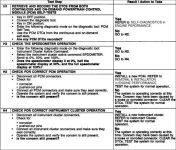
Have the car plugged into a good diagnostic scanner to check for fault codes stored on the BCM (body control module)
Principles of Operation
NOTE:Upon installation, a new instrument cluster must be reconfigured. For additional information, refer to MODULE CONFIGURATION .
The instrument cluster is a hybrid electronic cluster (HEC) with two basic configurations, the base cluster and the optional instrument cluster. In addition to the two basic configurations, the SVT uses a modified optional cluster in combination with a separate oil pressure and oil temperature cluster. The base instrument cluster, optional instrument cluster and the oil pressure and oil temperature cluster receive and output information utilizing both hardwired circuitry and the standard corporate protocol (SCP) or the controller area network (CAN) communication network (2.3L only).
An additional feature of the SVT instrument cluster and oil pressure and oil temperature cluster configuration is the use of an electro-luminescent backlighting strategy. The electro-luminescent backlighting utilizes switched DC to high AC voltage circuitry. The oil pressure and oil temperature cluster converts 12V DC into AC voltage that is variable up to 180V AC through the dimmer switch control.
CAUTION:The SVT instrument cluster utilizes high AC voltage for the electro-luminescent backlighting system in both the instrument cluster and oil pressure and oil temperature cluster. Care must be exercised when making measurements to the instrument cluster circuits.
It is very important to understand:
where the input originates from.
all the information necessary in order for a feature to operate.
which module(s) receive(s) the input or command message.
does the module which received the input control the output of the feature, or does it output a message over the SCP or CAN network to another module?
which module controls the output of the feature.
The instrument cluster carries out a display prove-out to verify that the warning/indicator miniature bulbs for monitored systems are functioning correctly. When the ignition switch is placed in the ON position with the engine off, the following warning indicators will prove out:
check transmission indicator
malfunction indicator lamp (MIL) indicator
oil pressure indicator
safety belt warning indicator
door ajar warning indicator
The following indicators are also displayed during prove-out but are not controlled by the instrument cluster:
anti-lock brake system (ABS) warning indicator
O/D OFF indicator
air bag warning indicator
brake warning indicator
charging system warning indicator
shift up indicator
low fuel warning indicator
traction control indicator
CHECK FUEL CAP indicator
speed control indicator
Tachometer
Engine speed data is transmitted to the instrument cluster from the powertrain control module (PCM) over the SCP or CAN communication network.
Speedometer
The instrument cluster receives the vehicle speed signal from the PCM over the SCP or CAN communication network and displays it on the speedometer gauge. If the instrument cluster receives no vehicle speed signal the speedometer defaults to 0.0 km/h (0.0 mph).
Fuel Gauge
The instrument cluster receives the fuel level information from the fuel sender unit (part of the fuel pump module). This is a variable resistor which varies the ground supply to the gauge. When the fuel level is low, the resistance is low, when the fuel level is high the resistance is high. If an invalid input signal is received, the fuel gauge will then default to below the empty position. The fuel level input signal is heavily damped to allow for movement of fuel in the tank when the ignition switch is in the ON position.
Temperature Gauge
Engine coolant temperature information is received by the instrument cluster from the PCM over the SCP or CAN communication network. If the engine coolant temperature information is missing or invalid, the temperature gauge will indicate below the cold (C) position.
Odometer/Trip Odometer
The odometer and trip odometer are displayed in the integrated circuit LCD display. The instrument cluster records the total mileage of the vehicle, using information received from the PCM and electronically displays this information in the LCD. If this information is not received, the LCD will display all dashes.

Friday, November 27th, 2020 AT 4:47 PM
(Merged)


