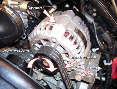
Most of the warning lights in the charging system work off a simple system. The light stays off if the voltage on both sides of the bulb is equal. The lamp connects to the alternator on one end and the ECU or regulator circuit on the other. Key on engine off the light comes on because one side of it is fed from the battery and the other side in the alternator acts like a ground because it isn't generating power. Start the engine and if the alternator is putting out the same or higher voltage than the sense circuit, the light goes out. If it is at least a volt lower, then the light comes on. The catch in modern vehicles is that commonly it takes more than the volt drop and due to the way they feed the control circuit, if you have a bad diode in the alternator that can back feed enough voltage that the light stays off even though it isn't charging. If you have a meter, measure the voltage at the battery with everything off, now start the engine, if you are seeing the same voltage now the alternator isn't charging. Switch your meter to AC and measure again. This checks the AC ripple, you should see at most a couple millivolts, if you see more the diode bridge has an issue, and replacement is needed.
In the diagram the CH wire is the heavy lead that connects the alternator to the charging stud and the battery positive. The Pwr wire is a 12-volt feed that is used to both power the regulator and as a sense lead for battery voltage independent of the ECM control. It's supposed to act as a fail-safe if the regulator control in the ECM fails, you would know if it was in control because it normally locks the output to about 14.5-15 volts if the engine is running. The S is the sense or monitor wire, this is the one that tells the ECM the voltage that is seen at the alternator, it is the one that controls the light as well. The last one is the com wire, this is the control for the regulator, it sends a PWM signal to turn the alternator on or off based on the draw on the electrical system. In the old days you could test the alternator using this terminal on the older alternators, if you grounded it out it would "full field" the alternator and it would drag the engine down as the alternator would produce the maximum voltage and current the unit could create. In many cases it is far more than the regulator ever could put out and you had to be sure that nothing other than the minimum was powered on because the high voltage could damage things (I've seen this test burn out light bulbs, burn off wires and do other assorted damage). It's why the test now is normally only done on the test bench, far too easy to fry the electronics if you suddenly dump 18 volts or more at full rated current though them!
Image (Click to make bigger)
Friday, November 22nd, 2024 AT 12:57 AM


