There is a Tech bulliten about a several water leaks, has this work been done yet? Also a recall to re calibrate(flash) the PCM, this is free on the recall. Here's the water leaks that can affect the PCM.
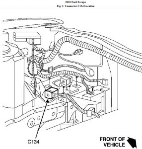
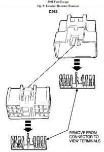
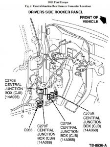
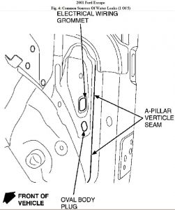
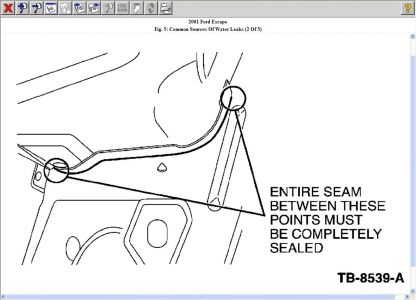
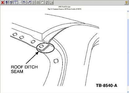
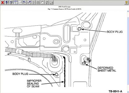
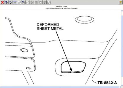
Follow the Service Procedure to inspect and repair the connector terminals for evidence of corrosion. Repair any sources of water entry. If no signs of corrosion or water entry are found, follow normal diagnostics. SERVICE PROCEDURE Inspect and repair the following connectors: C134 1. Open the hood and locate C134 ( Fig. 1 ). Fig. 1: Connector C134 Location 2. Disconnect the connector halves and thoroughly inspect the terminals. Clean any corrosion that may be present and replace any damaged terminals. 3. Use shop air to blow out any moisture that may be present in the terminals, then apply dielectric grease to the terminals in both halves of the connector. 4. Reconnect the connector halves and close the hood. C263 1. Open the drivers door and remove the lower kick panel. 2. Locate C263 as shown in Fig. 2 . Fig. 2: Central Junction Box Harness Connector Locations 3. Disconnect the connector halves. 4. Pry out the terminal retainer as shown in Fig. 3 and thoroughly inspect the terminals. Fig. 3: Terminal Retainer Removal 5. Clean any corrosion that may be present and replace any damaged terminals. 6. Work dielectric grease into the side opening in the connector, then reinstall the terminal retainer. 7. Apply dielectric grease to the terminals in both halves of the connector. NOTE: WHEN DIAGNOSING THE CAUSE OF A PCM FAILURE IT IS CRITICAL THAT THIS INSPECTION AND REPAIR PROCEDURE BE COMPLETED IN ITS ENTIRETY BEFORE INSTALLING A REPLACEMENT SERVICE PART. THE POSSIBILITY EXISTS FOR A 12 VOLT SHORT TO THE 5 VOLT VREF (CIRCUIT). INSTALLATION OF A SERVICE REPLACEMENT PCM WITHOUT ELIMINATING THE 12 VOLT SHORT WILL RESULT IN REPEAT PCM FAILURE. NOTE: THE CORROSION WILL NOT BE VISIBLE UNLESS THE TERMINAL RETAINER IS REMOVED. 8. Reconnect the connector halves. CJB (CENTRAL JUNCTION BOX) 1. Locate the CJB ( Fig. 2 ). 2. Disconnect the four harness connectors from the front and the two connectors from the rear of the CJB, and remove the CJB. 3. Inspect the terminals and also the back side of the CJB or evidence of water damage or corrosion. 4. Clean any corrosion that may be present and replace any damaged terminals or components. 5. Apply dielectric grease to the terminals in the harness connectors. 6. Reconnect the six harness connectors and reinstall the CJB. 7. Reinstall the lower kick panel. Follow standard water testing procedures to identify the source of any leaks. Figures 4 through 8 identify some common sources of water leaks. Fig. 4: Common Sources Of Water Leaks (1 Of 5) Fig. 5: Common Sources Of Water Leaks (2 Of 5) Fig. 6: Common Sources Of Water Leaks (3 Of 5) Fig. 7: Common Sources Of Water Leaks (4 Of 5) Fig. 8: Common Sources Of Water Leaks (5 Of 5) PARTS INFORMATION PARTS INFORMATION WARRANTY INFORMATION NOTE: IF ANY CORROSION WAS FOUND IN EITHER C263 OR THE CJB, THE SOURCE OF THE WATER ENTRY MUST BE IDENTIFIED TO PREVENT A REPEAT REPAIR. Part Number Part Name XG-12 Electrical Grease
4/24/2010 ...
Saturday, April 24th, 2010 AT 6:12 AM


