110) DTC P1409 This DTC indicates self-test has detected electrical malfunction in EGRVR circuit. Possible causes are: Ã Â Â EGRVR circuit open or shorted. Ã Â Â Faulty EGRVR solenoid. Ã Â Â Faulty PCM. Turn ignition off. Disconnect EGRVR solenoid connector. Measure resistance between EGRVR solenoid terminals. If resistance is 26-40 ohms, go to next step. If resistance is not 26- 40 ohms, replace EGR VR solenoid. 111) Check VPWR To EGRVR Solenoid Turn ignition on. Measure voltage between VPWR terminal at EGRVR solenoid wiring harness connector and chassis ground. See Fig. 116 . If voltage is more than 10.5 volts, go to next step. If voltage is 10.5 volts or less, repair open in VPWR circuit. 112) Check EGRVR Circuit Continuity Turn ignition off. Disconnect PCM 104-pin connector. Inspect connector for loose, damaged or corroded terminals. Repair as necessary. Measure resistance between PCM connector pin No. 47 and EGRVR terminal at EGRVR solenoid wiring harness connector. If resistance is less than 5 ohms, go to next step. If resistance is 5 ohms or more, repair open in EGRVR circuit. 113) Check EGRVR For Short To PWR Turn ignition on. Measure voltage between PCM connector pin No. 47 and negative battery terminal. If voltage is less than one volt, go to next step. If voltage is one volt or more, repair short to power in EGRVR circuit. 114) Check EGRVR For Short To PWR GND Turn ignition off. Measure resistance between PCM connector pins No. 47 and 103 (PWR GND). If resistance is less than 10,000 ohms, repair short circuit. If resistance is 10,000 ohms or more, replace PCM. 120) Continuous Memory DTC P1409 This DTC indicates self-test has detected electrical malfunction in EGRVR circuit. Possible causes are: Ã Â Â EGRVR circuit open or shorted. Ã Â Â Faulty EGRVR solenoid. Ã Â Â Faulty PCM. NOTE: A break in step numbering sequence occurs at this point. Procedure skips from step 114 to step 120). No test procedures have been omitted.
Turn ignition off. Disconnect PCM 104-pin connector. Inspect connector for loose, damaged or corroded terminals. Repair as necessary. Turn ignition on. Measure voltage between PCM connector pins No. 47 and 103 (PWR GND). Voltage should be more than 10.5 volts. Observe DVOM for indication of fault while wiggling EGRVR solenoid wiring harness and connector. Fault is indicated by a sudden drop in voltage reading. Tap lightly on EGRVR solenoid to simulate road shock. If fault is indicated, isolate and repair as necessary. If no faults are indicated, unable to duplicate or identify fault at this time. Go to TEST Z .

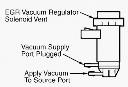
This is what the EVR looks like.

This is fig 116
This is the PCM Plug Identification.

SPONSORED LINKS
Friday, August 28th, 2009 AT 7:33 PM


